ESTLCAM – 2.5D Routing- Intermediate
This is an intermediate walk through on 2.5D routing with ESTLCAM. You should have a firm grasp on the basics before trying this. This is how to manually set up a 2.5D cut, the alternative would be to import an STL file and let ESTLCAM choose the paths. The automatically generated STL paths took 50 minutes to cut and did not pick up the small 4mm hole. The following manual paths took 18 minutes to cut and look fantastic!
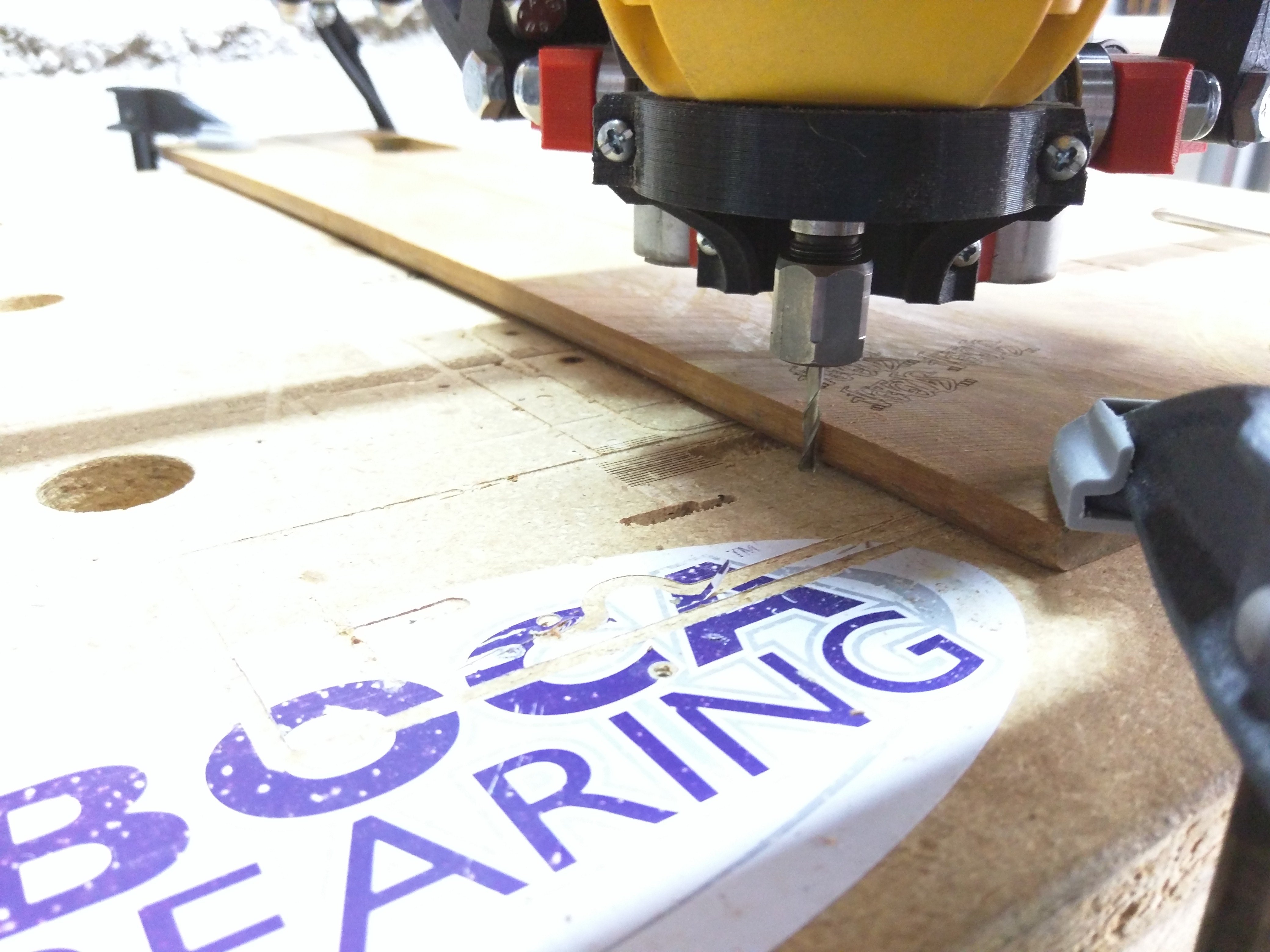
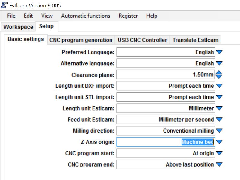
So I can show some different techniques in this walk though I am using piece of Brazilian Ipe that has an uneven top surface, so no reliable Z origin. I will use the bed as the start position and tell ESTLCAM the work surface is slightly higher than measured on the thickest part of the wood. This will allow me to easily surface the uneven wood and not have to estimate where the origin should be.
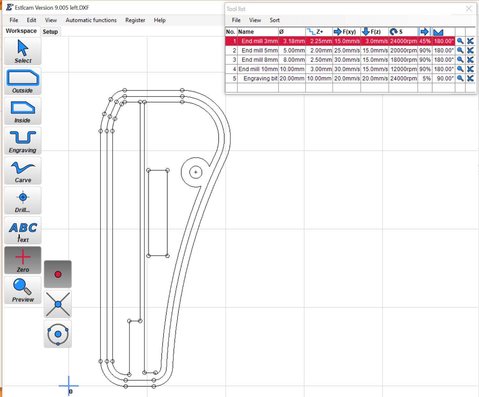
The tool paths start with importing the DXF file in mm. This file has all the part paths on it but not the depth of cut so we will work though this one step at a time. The tool will be starting off to the left of the actual piece of wood touching the bed so the first step is to move the zero point over about half an inch, to approximate where the tool will start. Just select Zero, Point, and Click where you want the new Zero.
These are the dimensions I will be using for the depths of cut.
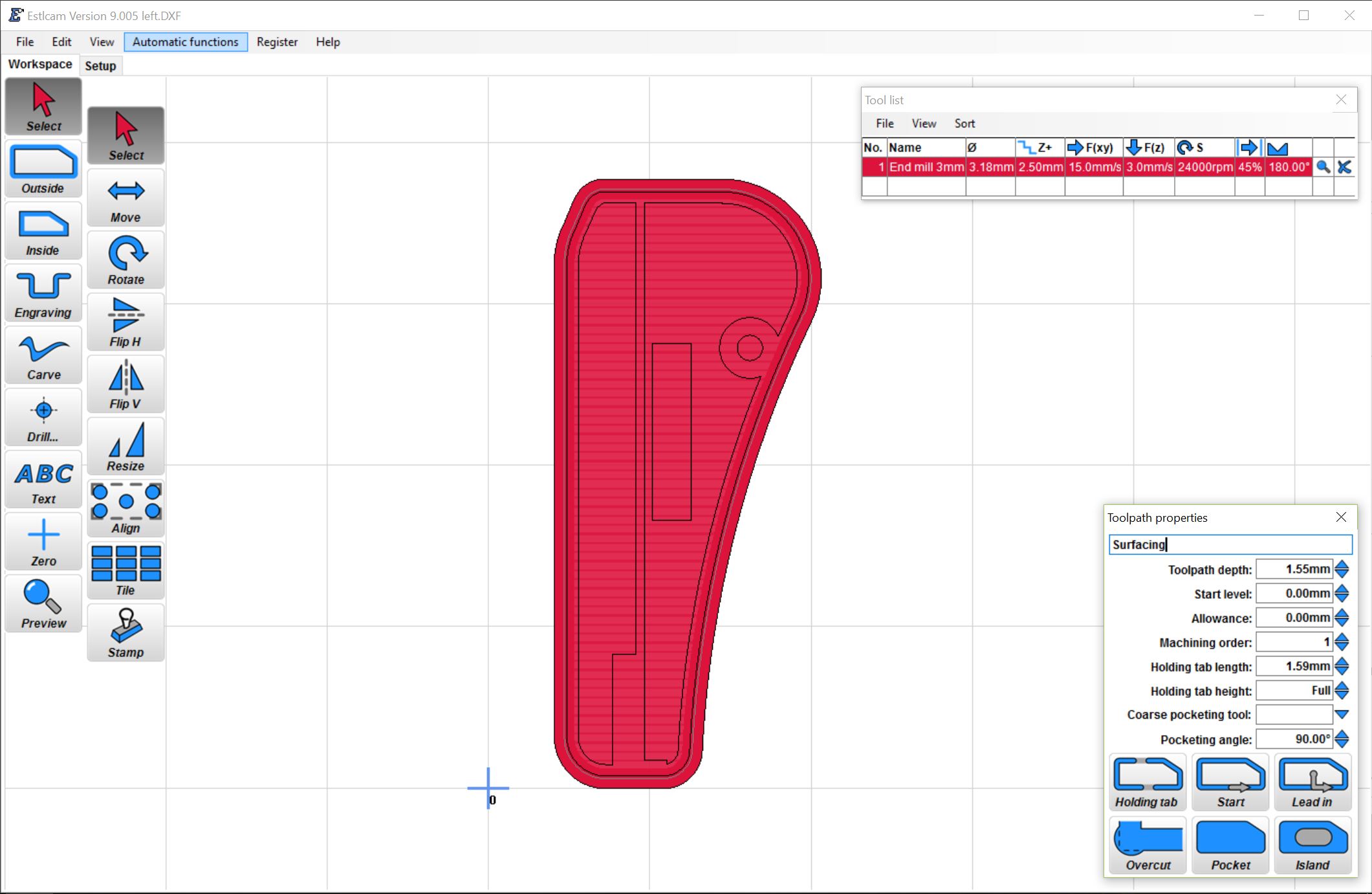
The first cutting step will be the basic surfacing of the wood to make sure the top is nice and flush. I don’t have much thickness to spare so for surfacing I am only cutting 1.55mm into the work surface. Because I am starting from the bed the Z origin will be set at the end when ESTLCAM asks for the part height, that will be the Z zero plane (I will be using 11.5mm). So for this part my Z=0 will be 11.5mm from the bed surface. If you had a nice flat piece of material you can make it easier and just start at the work surface.
For the cut I select Inside, pocket, and selected the outermost path, shown in red. Make sure to set the tool path depth and machining order starting at one and increment by at least one.
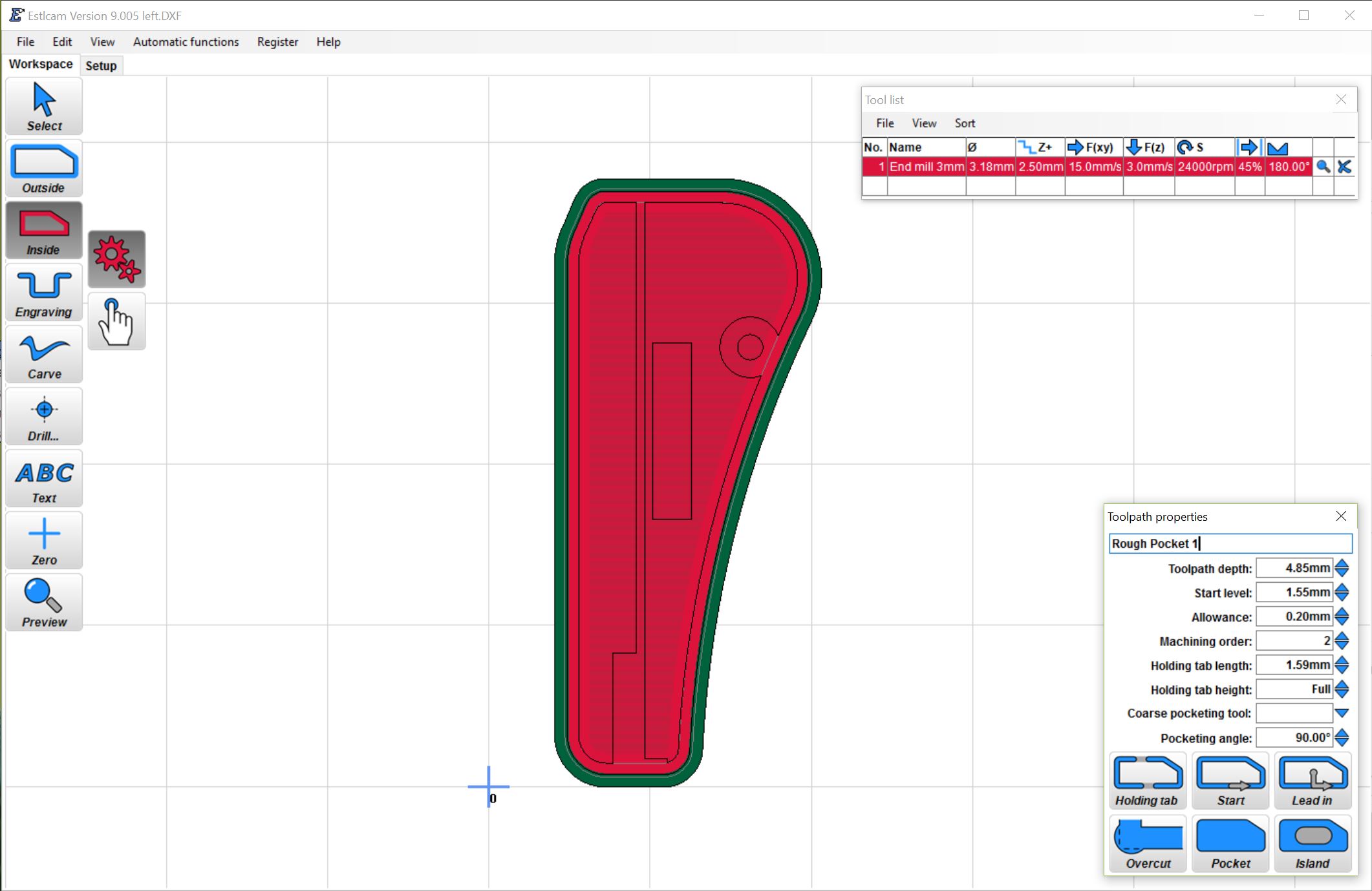
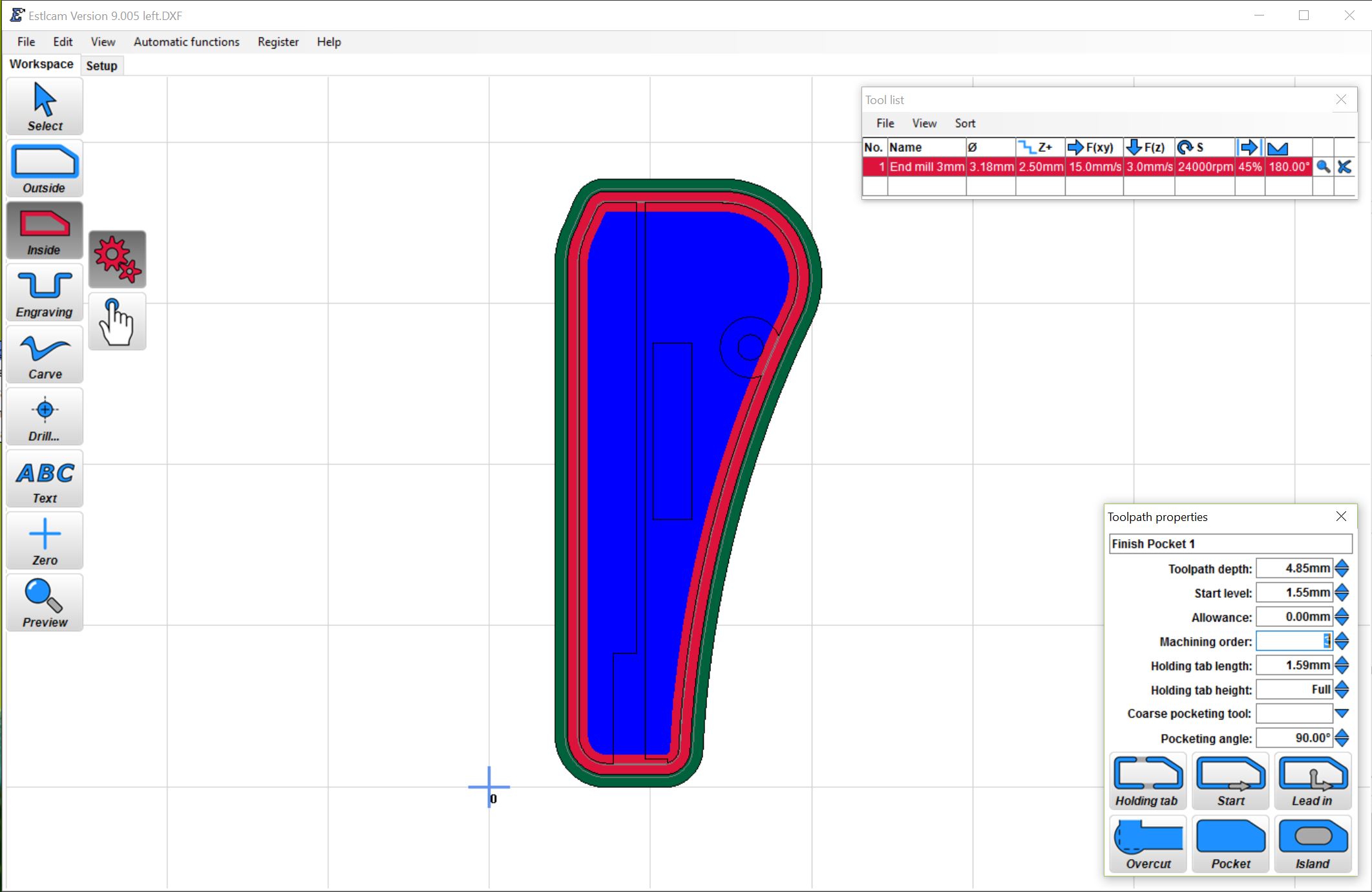
The next cut will be a pocket taking the whole surface down in 2 steps, a rough and finishing pass. For the roughing we can start at 1.55mm from the Z=0 plane since that material is already gone from the previous step and go into the material another 4.85mm as seen in the part dimensions. For the roughing pass we will leave an allowance of 0.2mm. This lets us come back round for a second pass and only have to mill of .2mm of wood and this leaves a nice smooth finished surface. So we use an inside pocket pass with .2mm allowance and then a second just inside cut with 0 allowance since the material has already been removed with the roughing pocket no need to cut all that empty space. Current tool path shown in red.
Again, always set the machining order. This new pocket will be the depth at which we start the rest of the cuts (6.4mm)
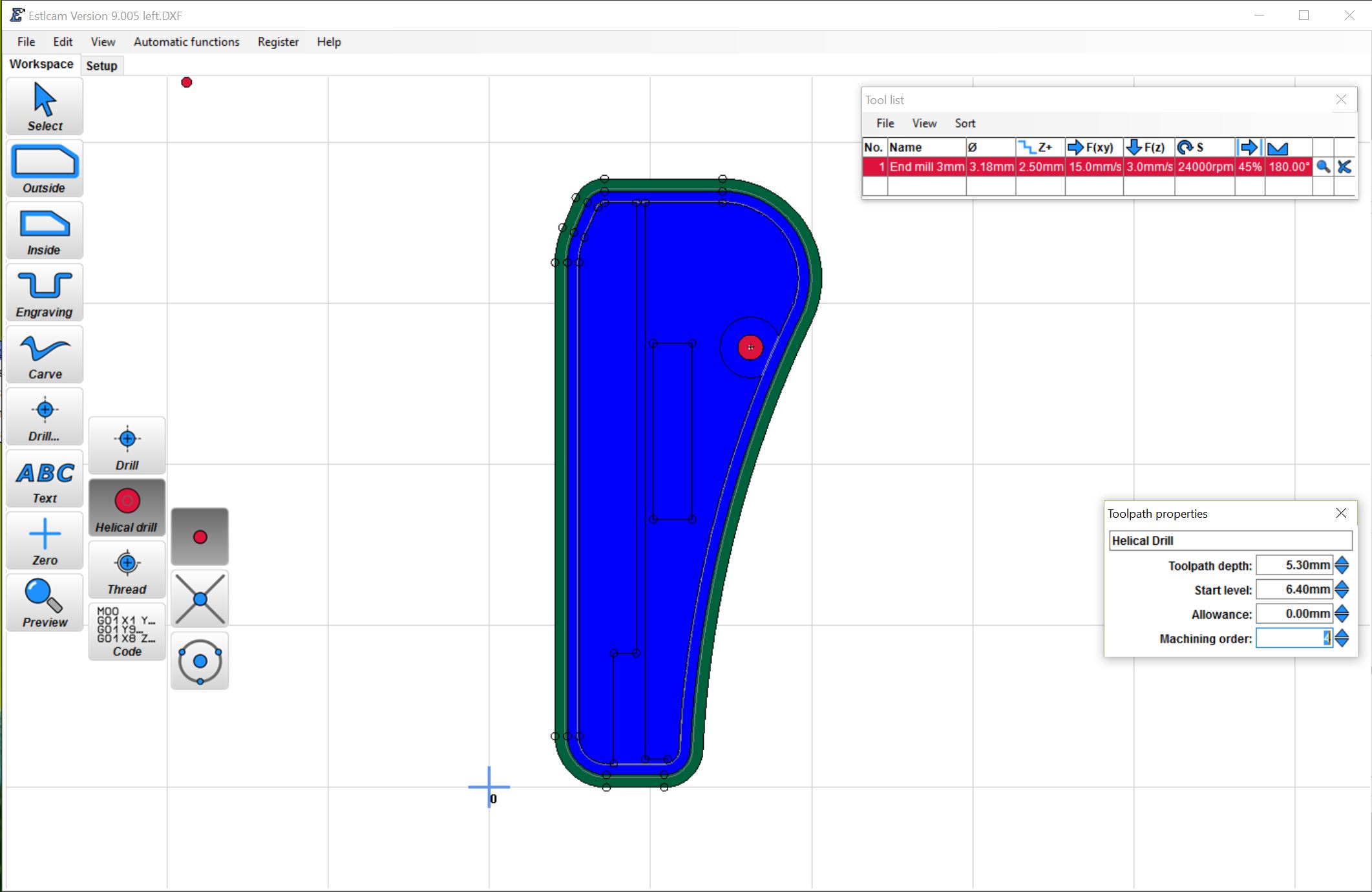
Next will be the 4mm hole. We can use a Helical path and start from 6.4mm deep and go a little into the spoil board, I went an extra .2mm for a cut of 5.3mm
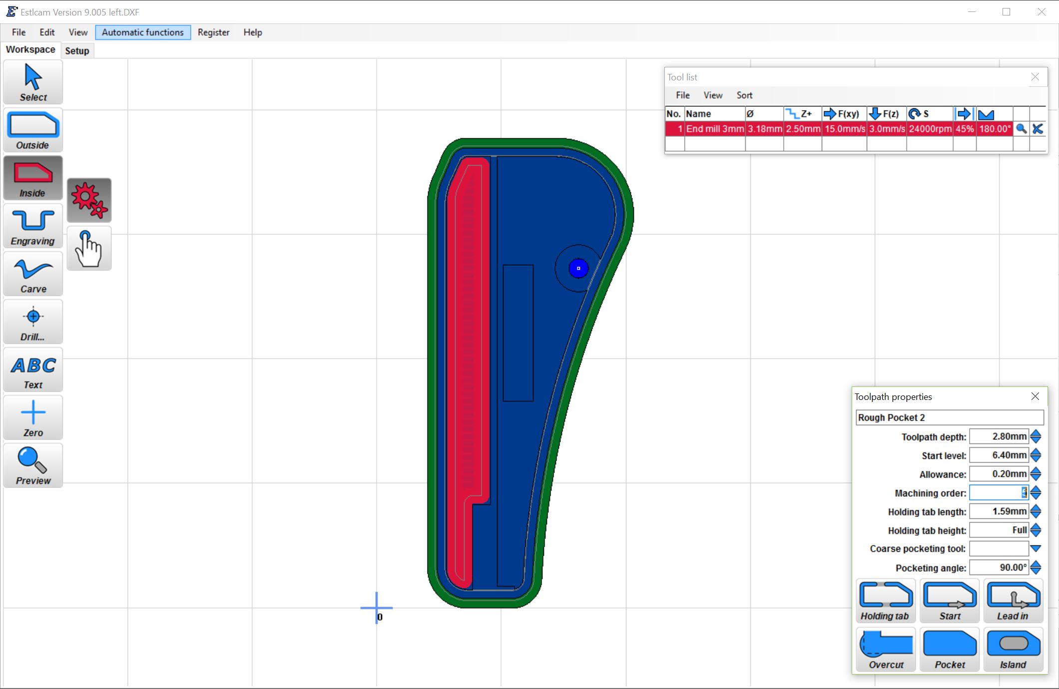
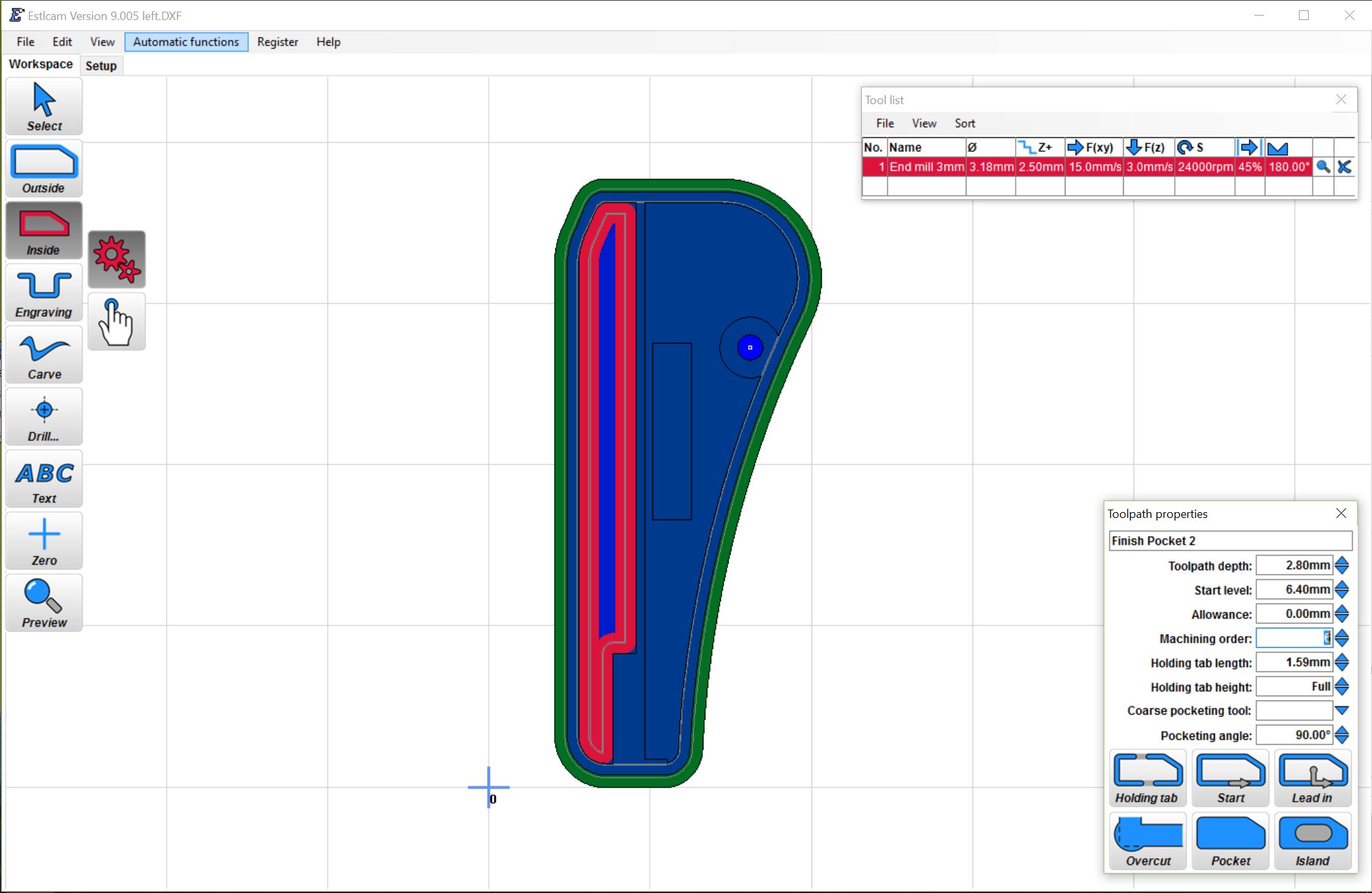
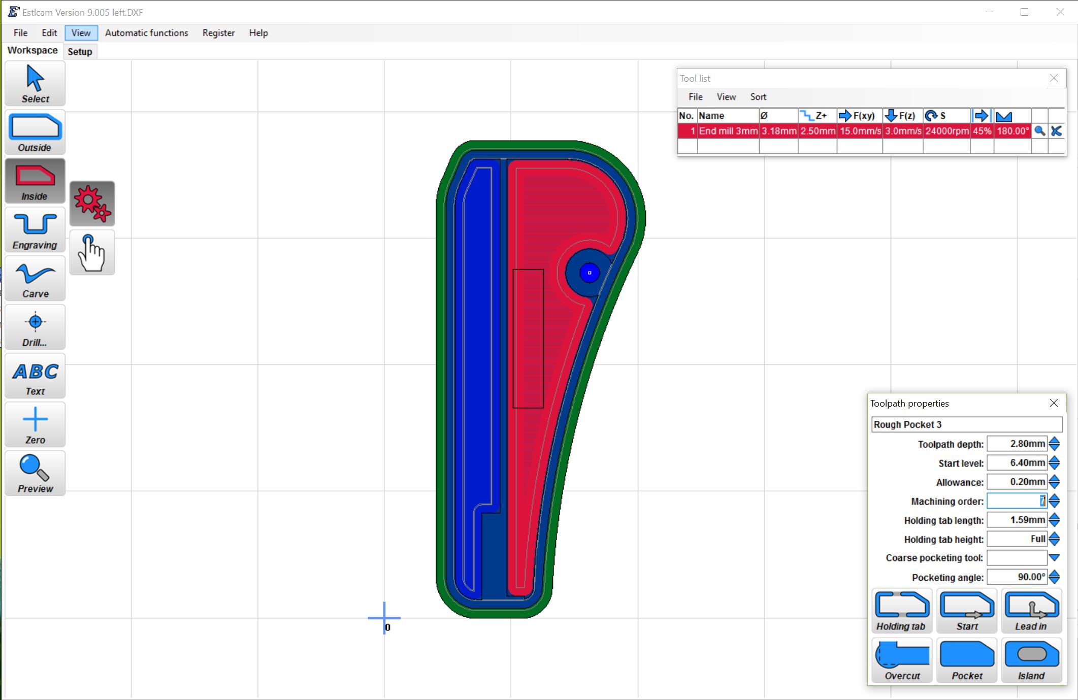
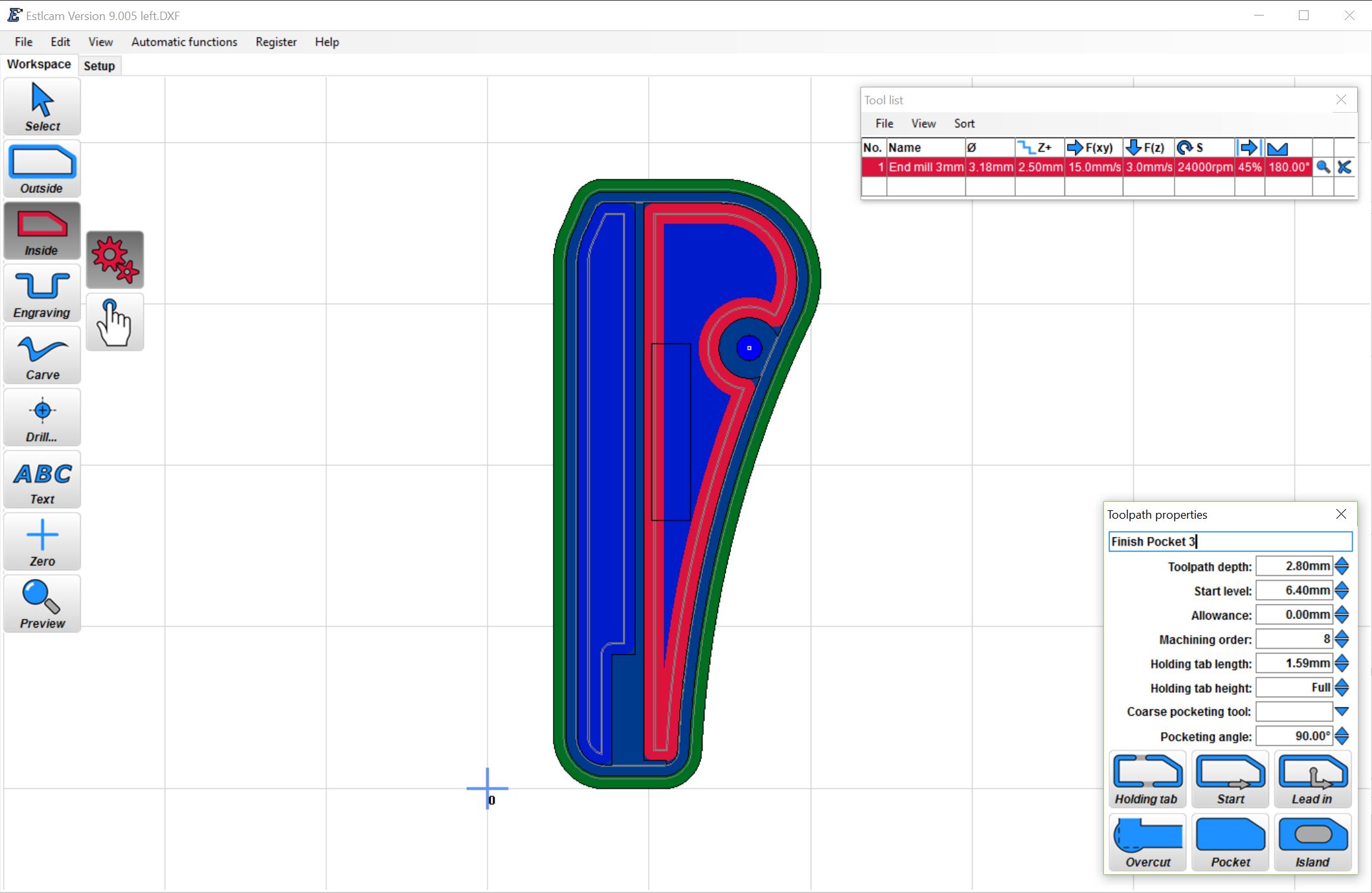
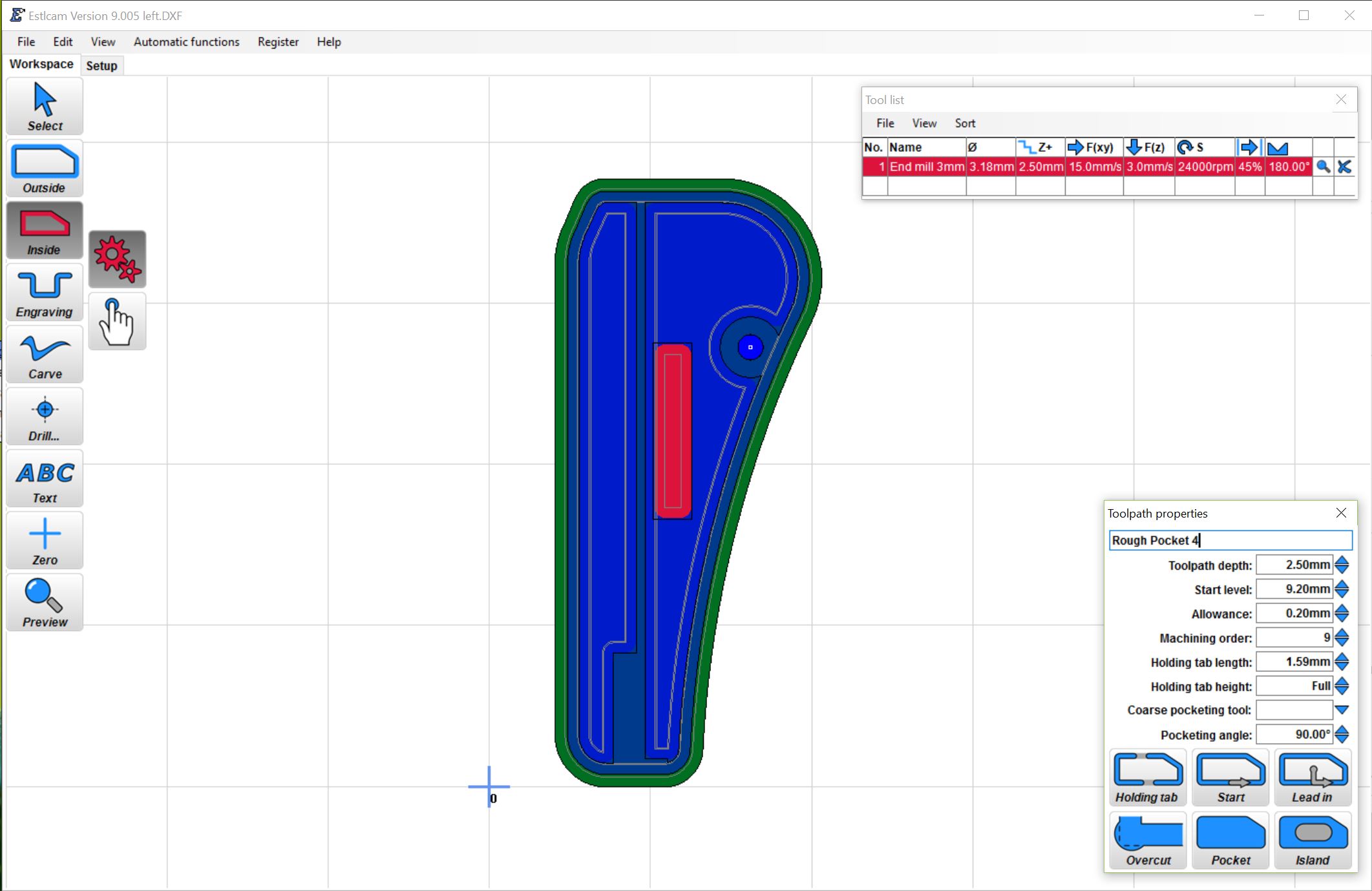
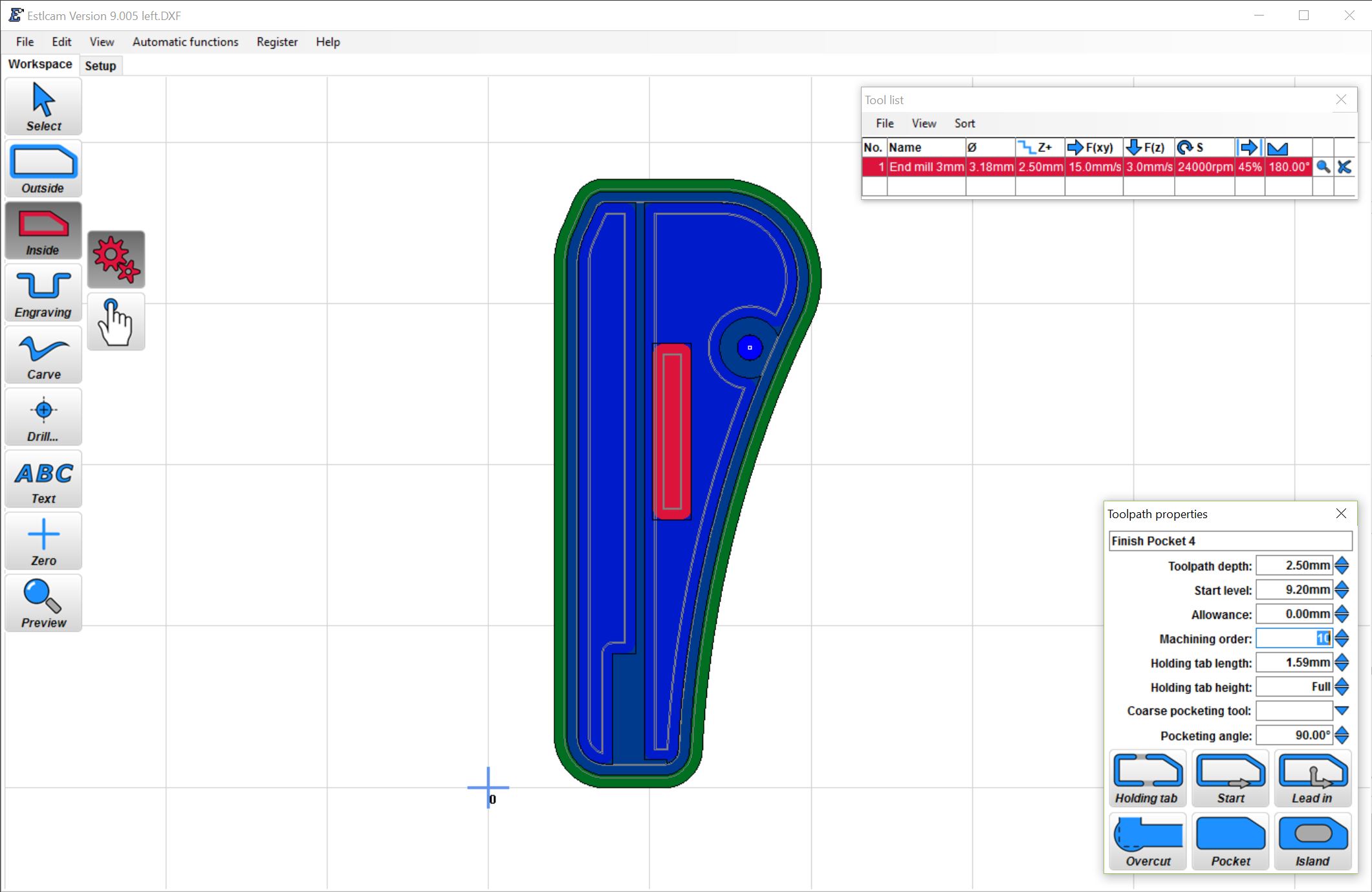
Now 3 more inside cuts, rough pockets followed by finishing passes.
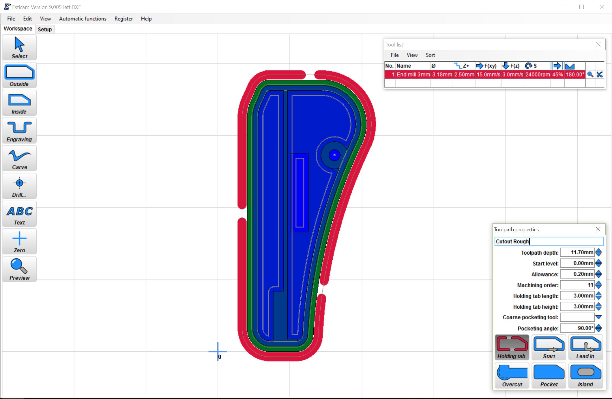
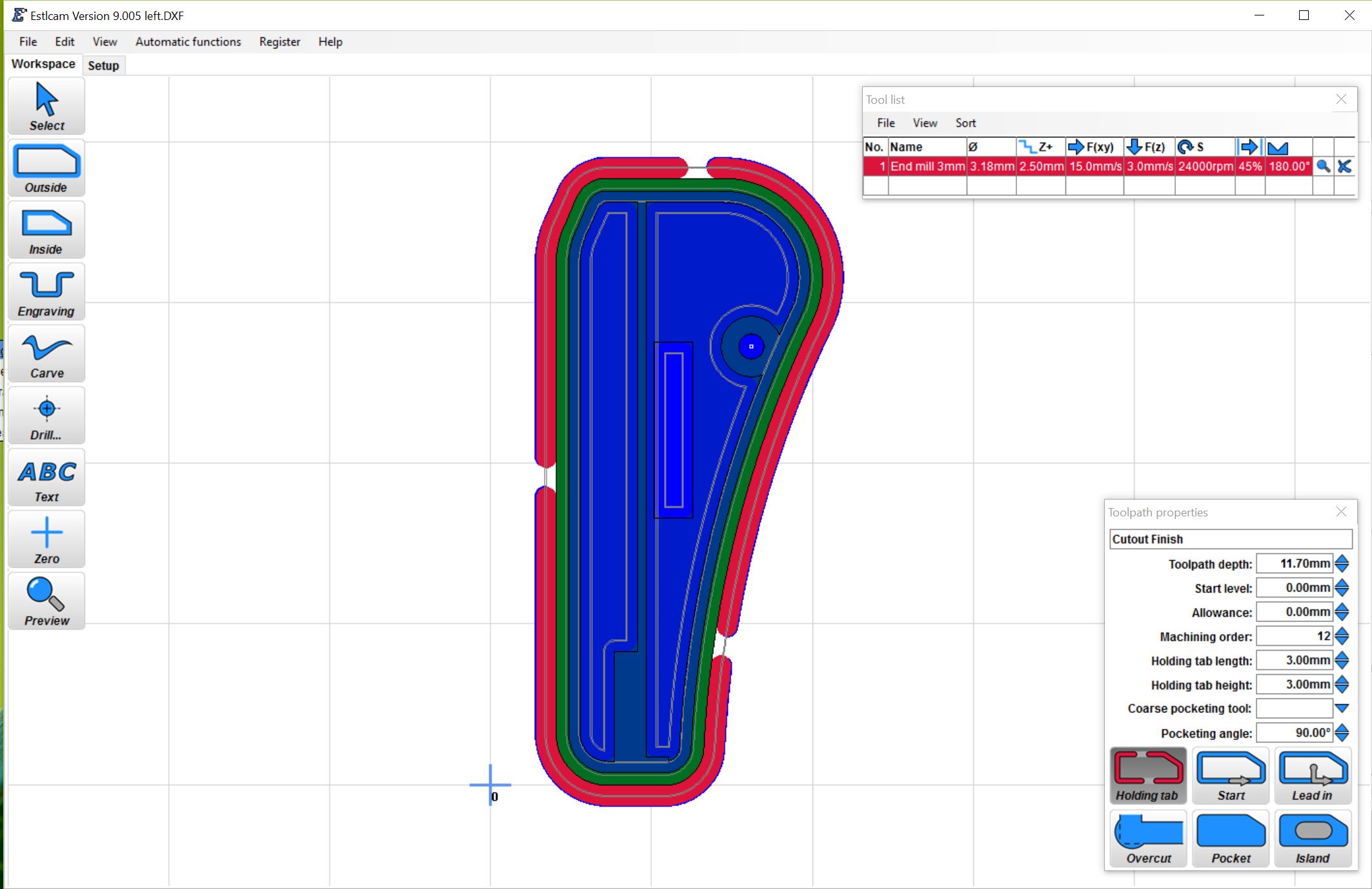
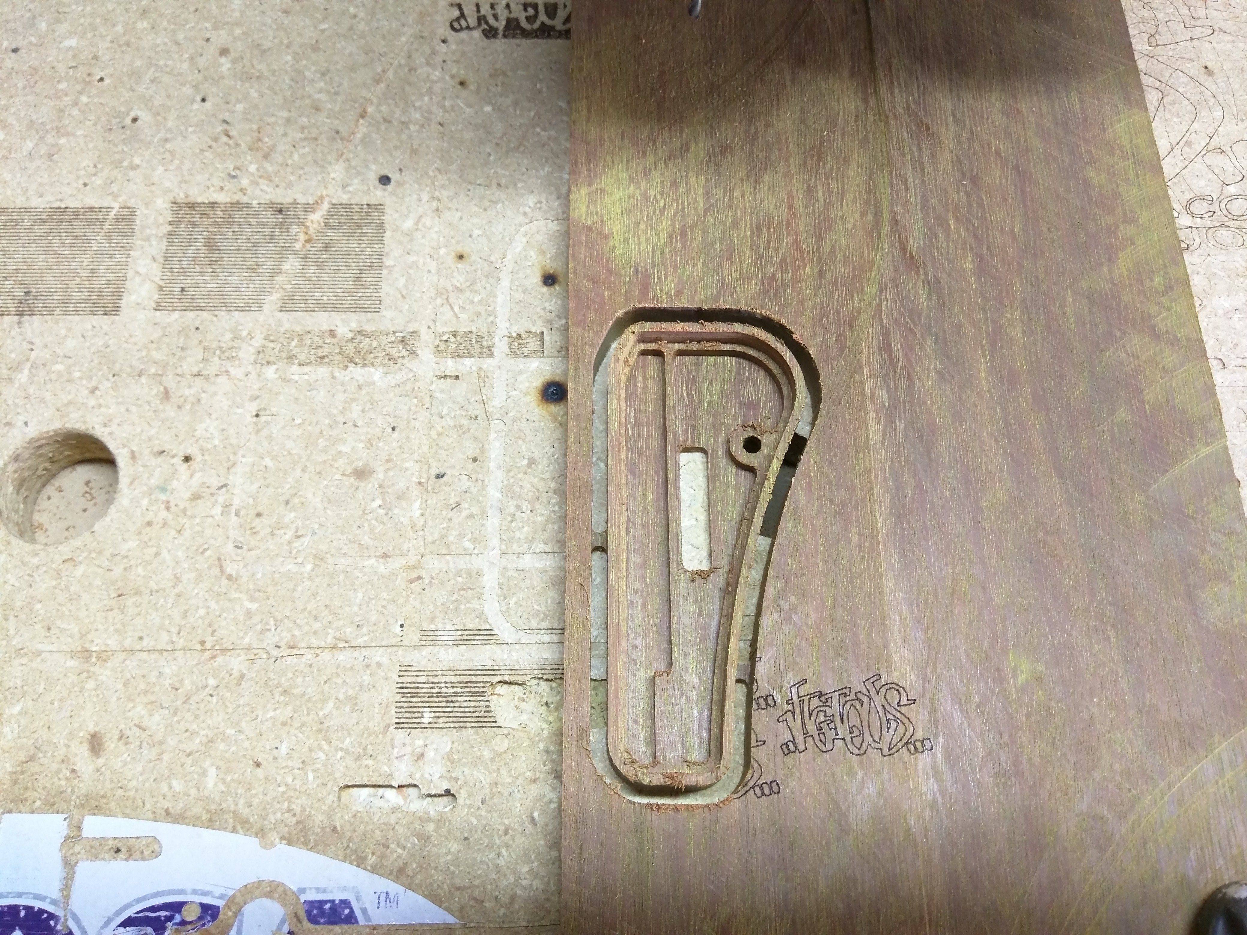
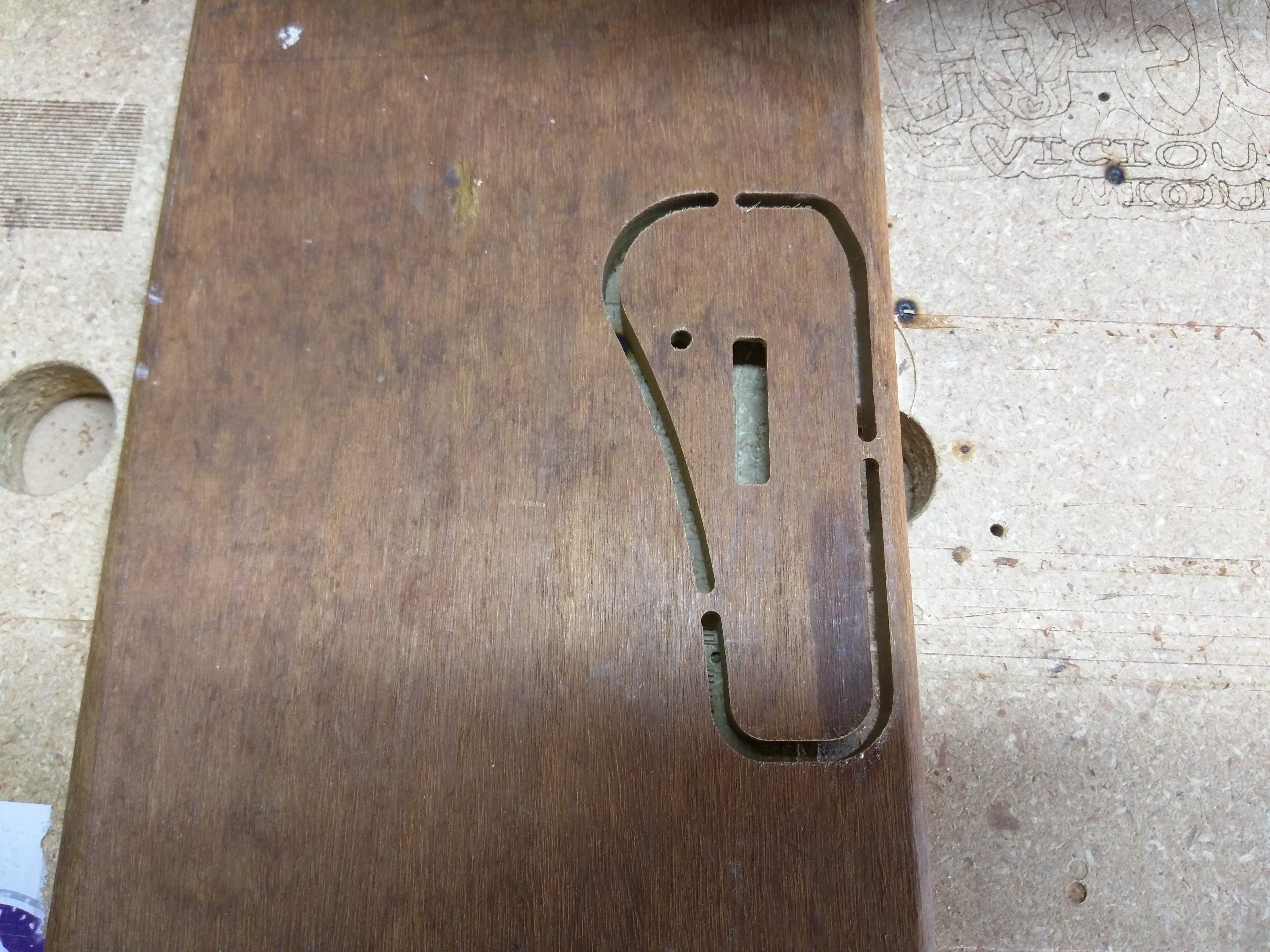
Now that the inner features have been finished it is time to cut the part from the material, leaving 3 small tabs that can easily be snipped off. For this step will be using an outside cut, with a .2mm allowance, setting the tabs, starting at the Z=0 plane since the outer edge did not get surfaced and cutting .2mm in to the waste board (11.7mm deep). Then the finishing pass with 0 allowance and matching the tabs previously set.
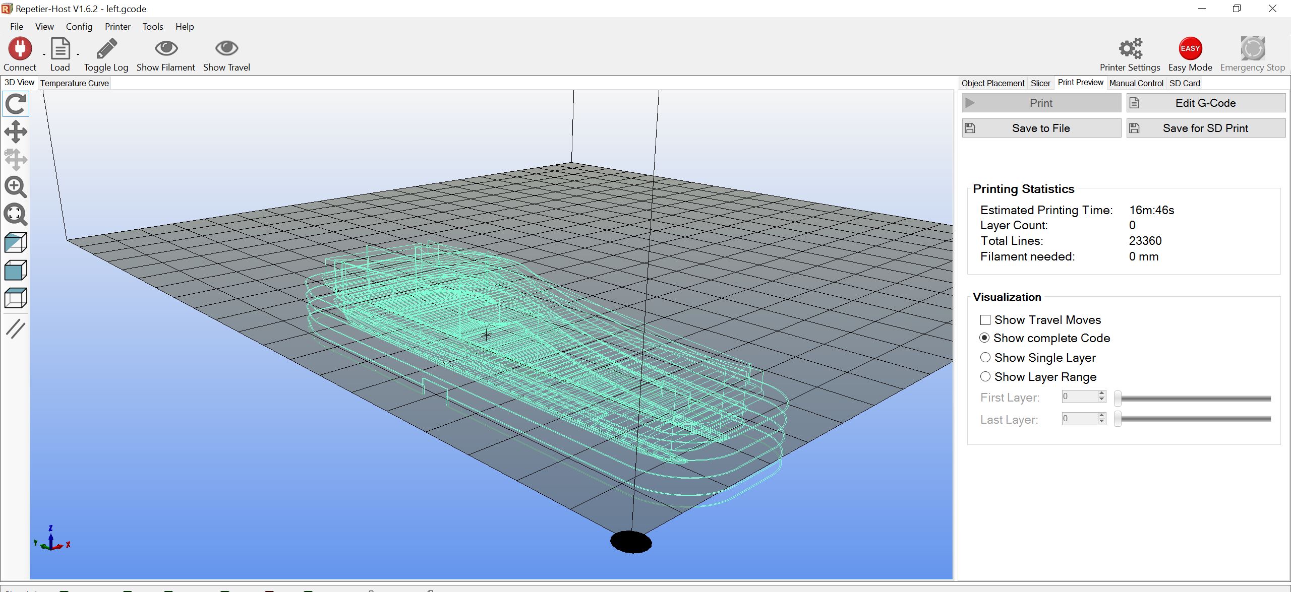
Now save your project in case you need to come back and edit your paths. You can do this by using the select tool and changing the popup box parameters. Then export your CNC program (gcode). I use repetier as my visualizer to make sure the cuts look like they should, but to catch small errors if you are new to this I always suggest cutting into high density foam the first run to test your path. Better to waste some time and foam than stress your machine, break a bit, and waste material with some bad gcode.
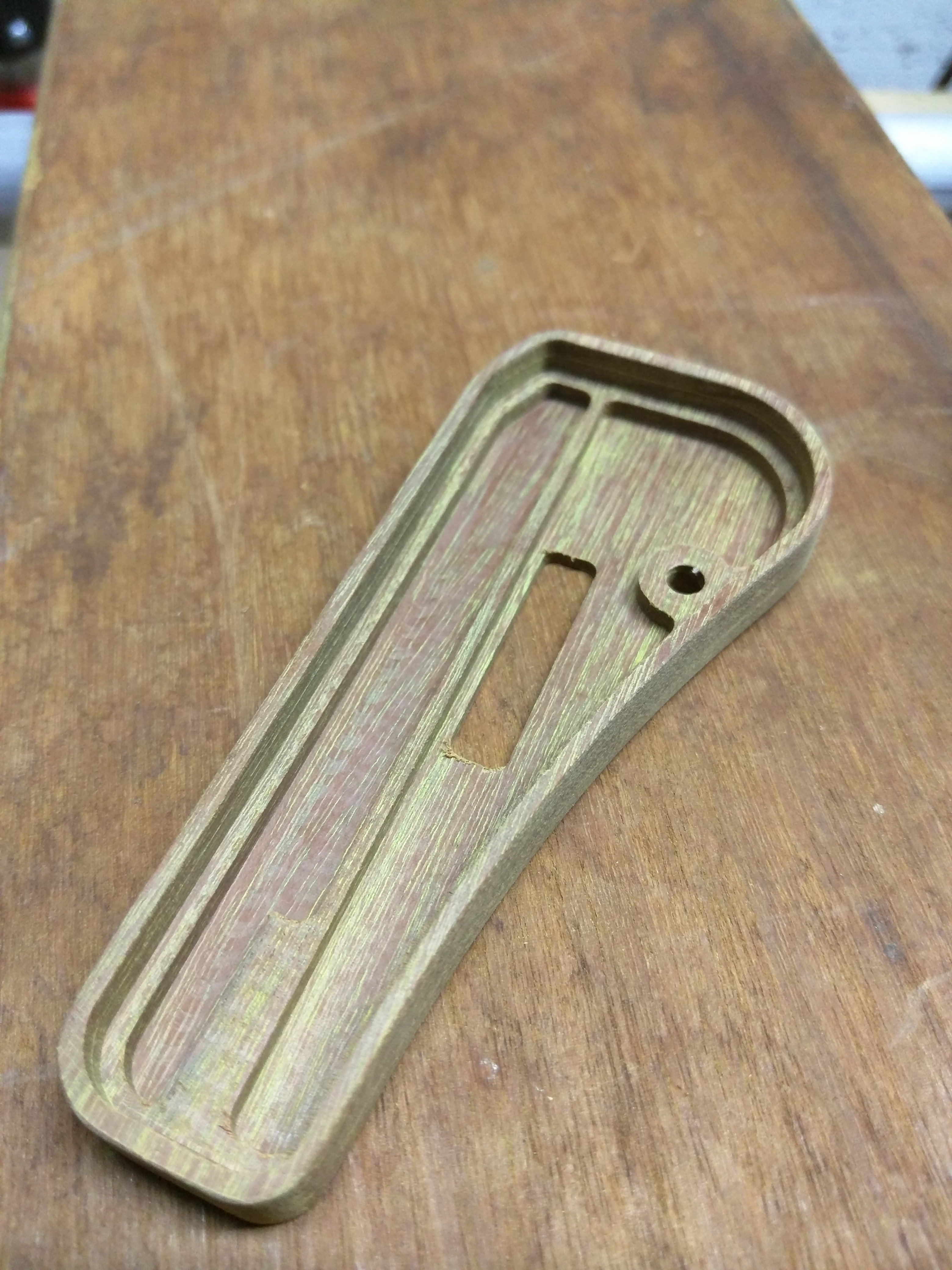
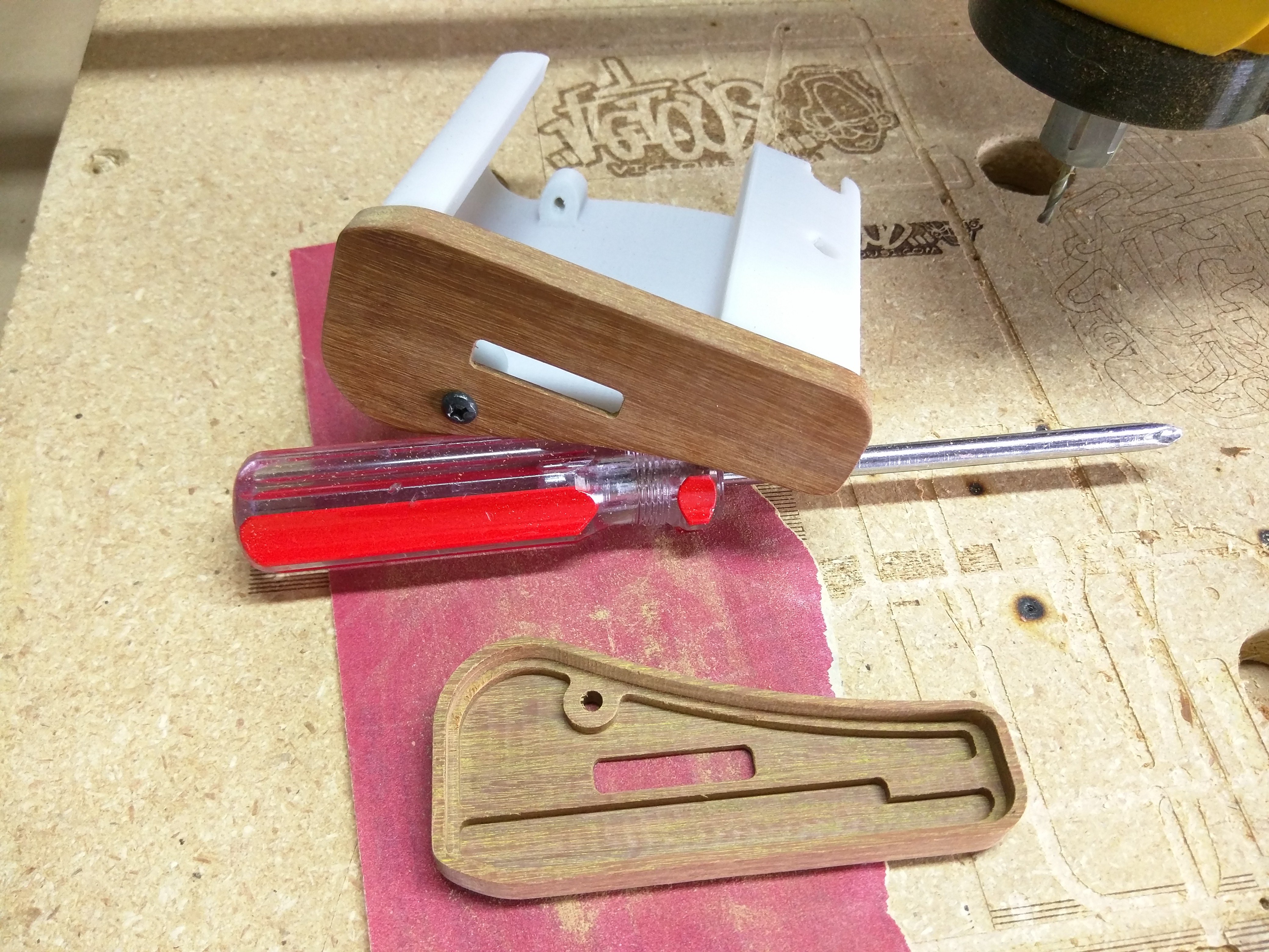
This leaves me with fairly finished part. I can pop it out and use a razor knife to cut off the tabs. I then hit the edges lightly with some 220 git sand paper and call it a day.
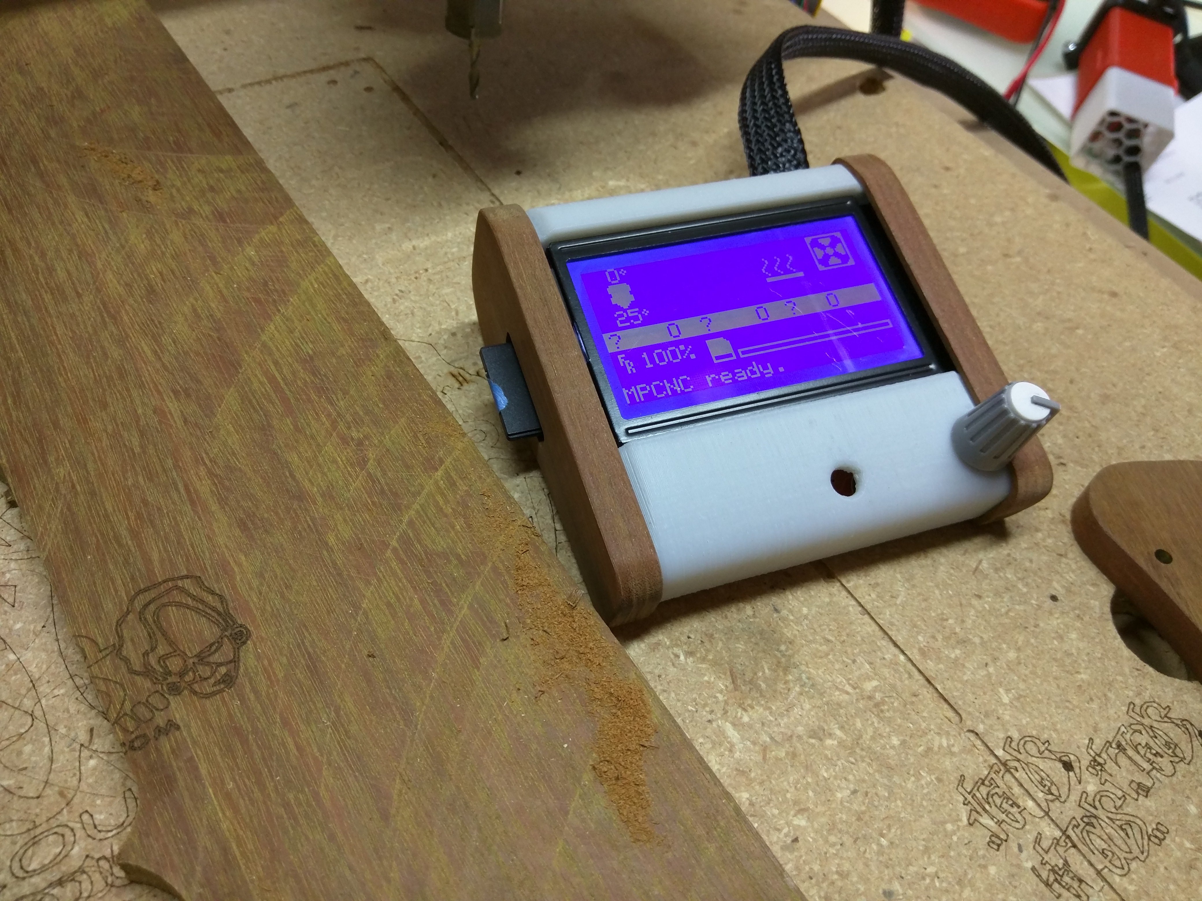
Here are the files I used; you will probably need to edit these unless your wood is 11.5mm thick. This is the DXF, My generated gcode, and my estlcam project file. This is one of the parts for this http://www.thingiverse.com/thing:1562144
Here is a video of this exact cut.
Now to make the other side of the case, flip the tool paths in estlcam (you might have to realign the tabs) and delete the SD card cuts. Here is the video for that,
Ask your Questions here,
https://forum.v1engineering.com/t/questions-for-the-intermediate-walk-through/4436
