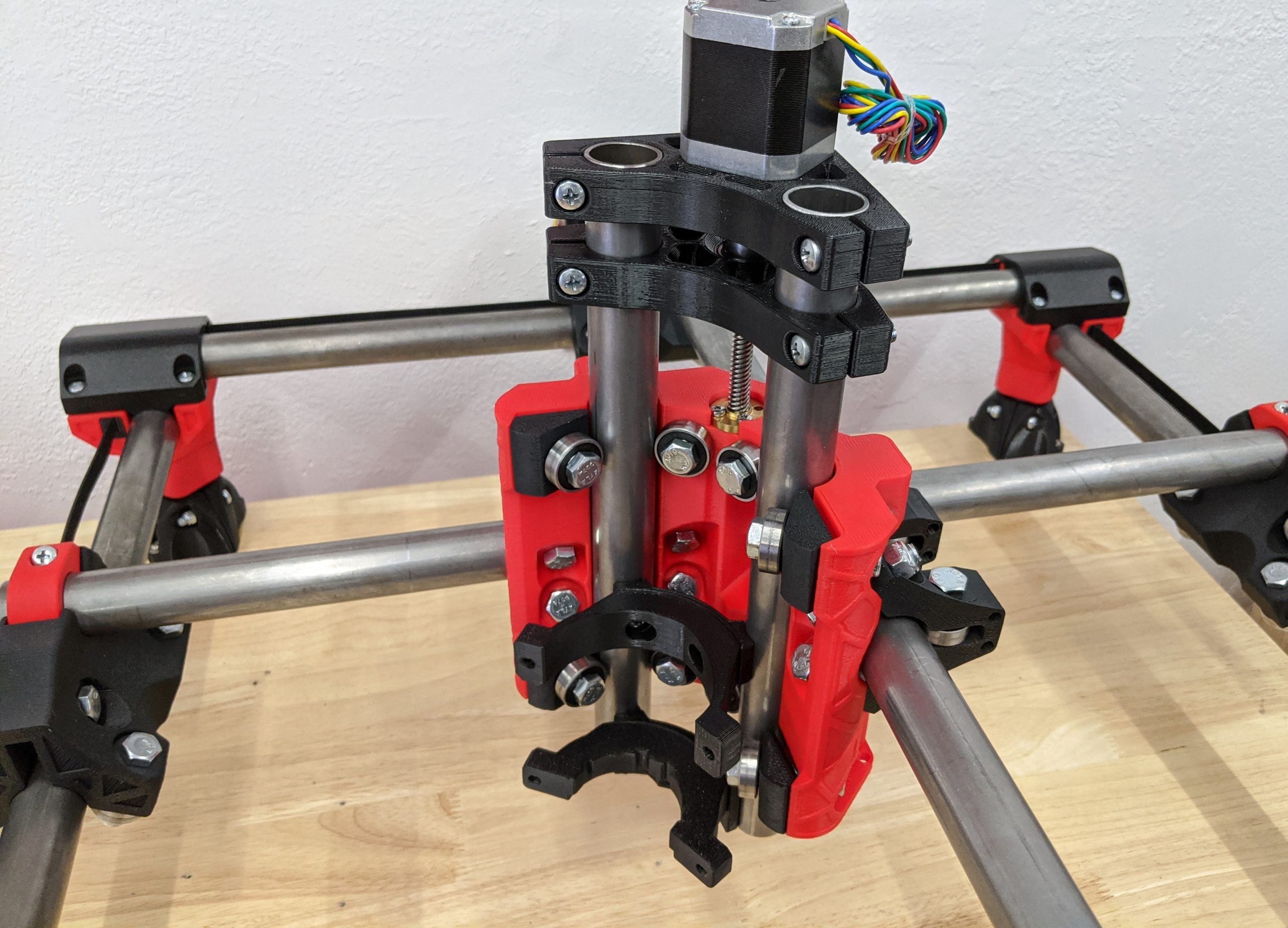
Z Axis
Z Rails
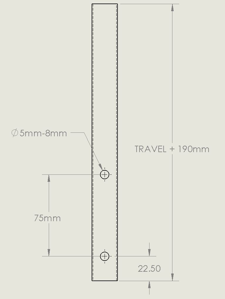
- Using the cut Calculator, determine your Z rail length.
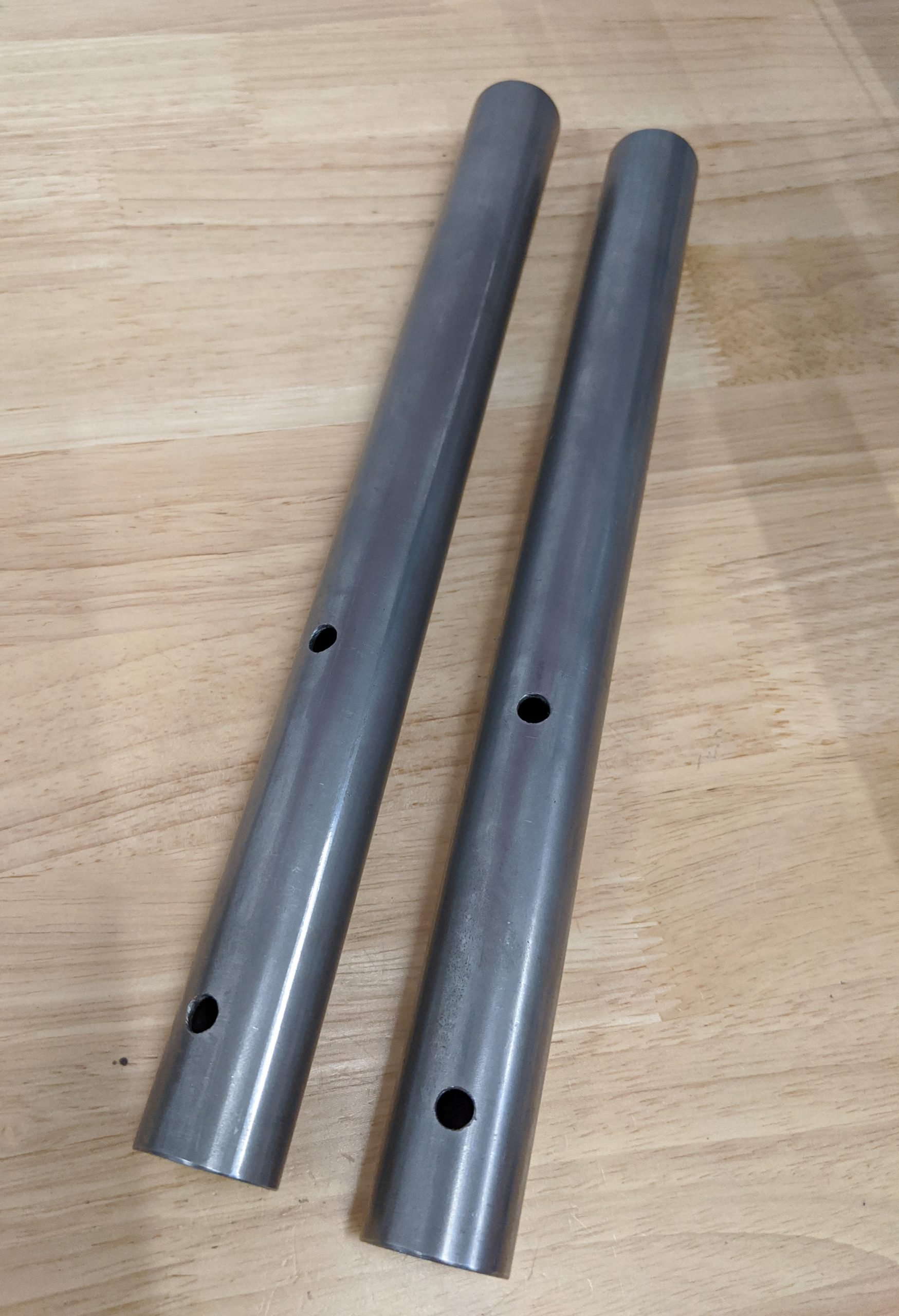
- You will need to drill 4 holes for M5 screws.
- It is best to oversize the holes (up to about 8mm is fine) to allow for some adjustment and non-perfect drilling.
Note
These are blind holes, do not drill through both sides of the tube
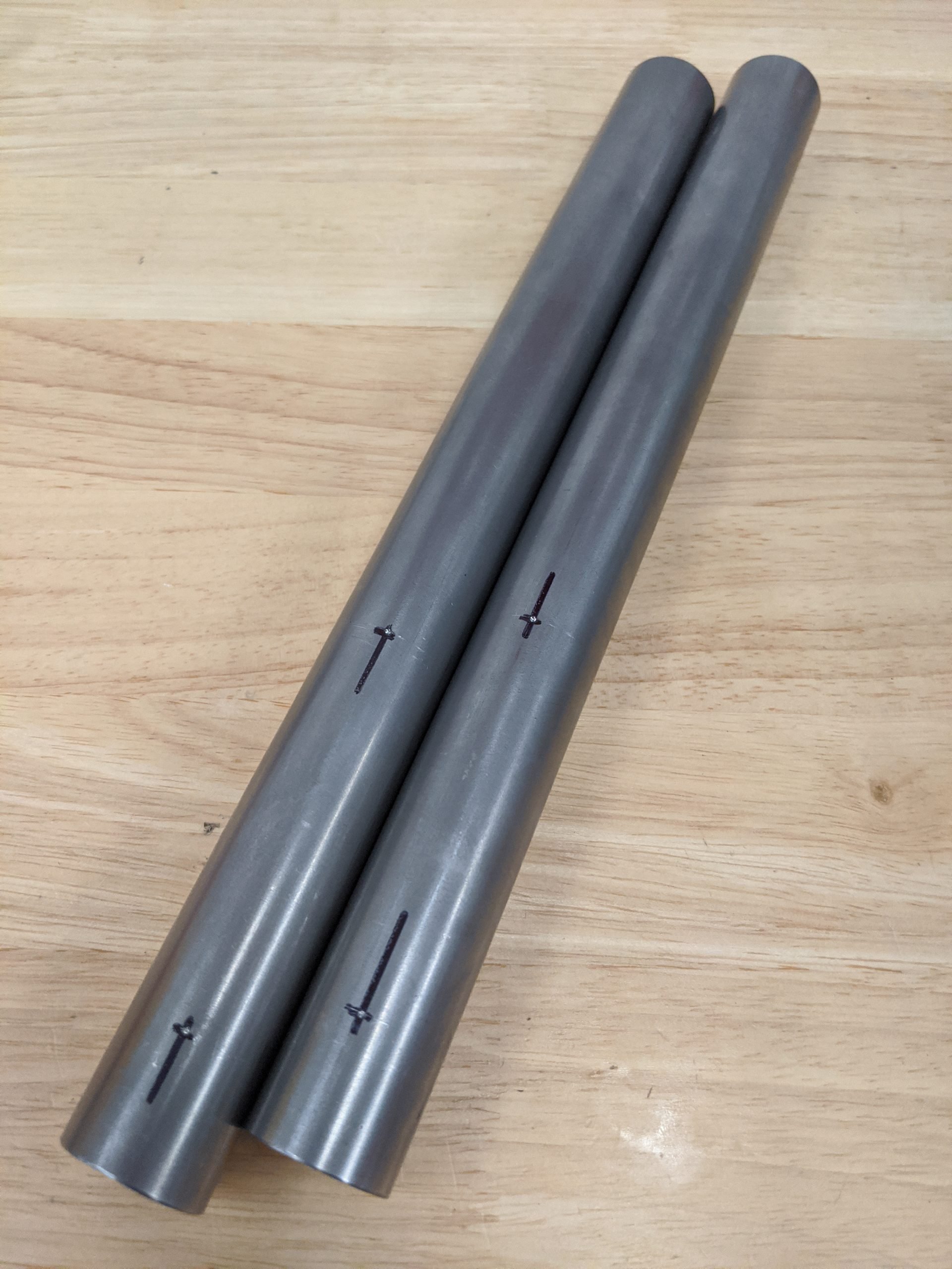
- Mark the rails according to the previous diagram.
- A center punch, center drill, or even filing a small flat spot helps with drilling accuracy.
Tip
You can draw a straight line on one rail using the other as a guide and/or a square block roughly half as high as the rail.
- Deburring the edges of the holes ensures good tool mount alignment.
Leadscrew
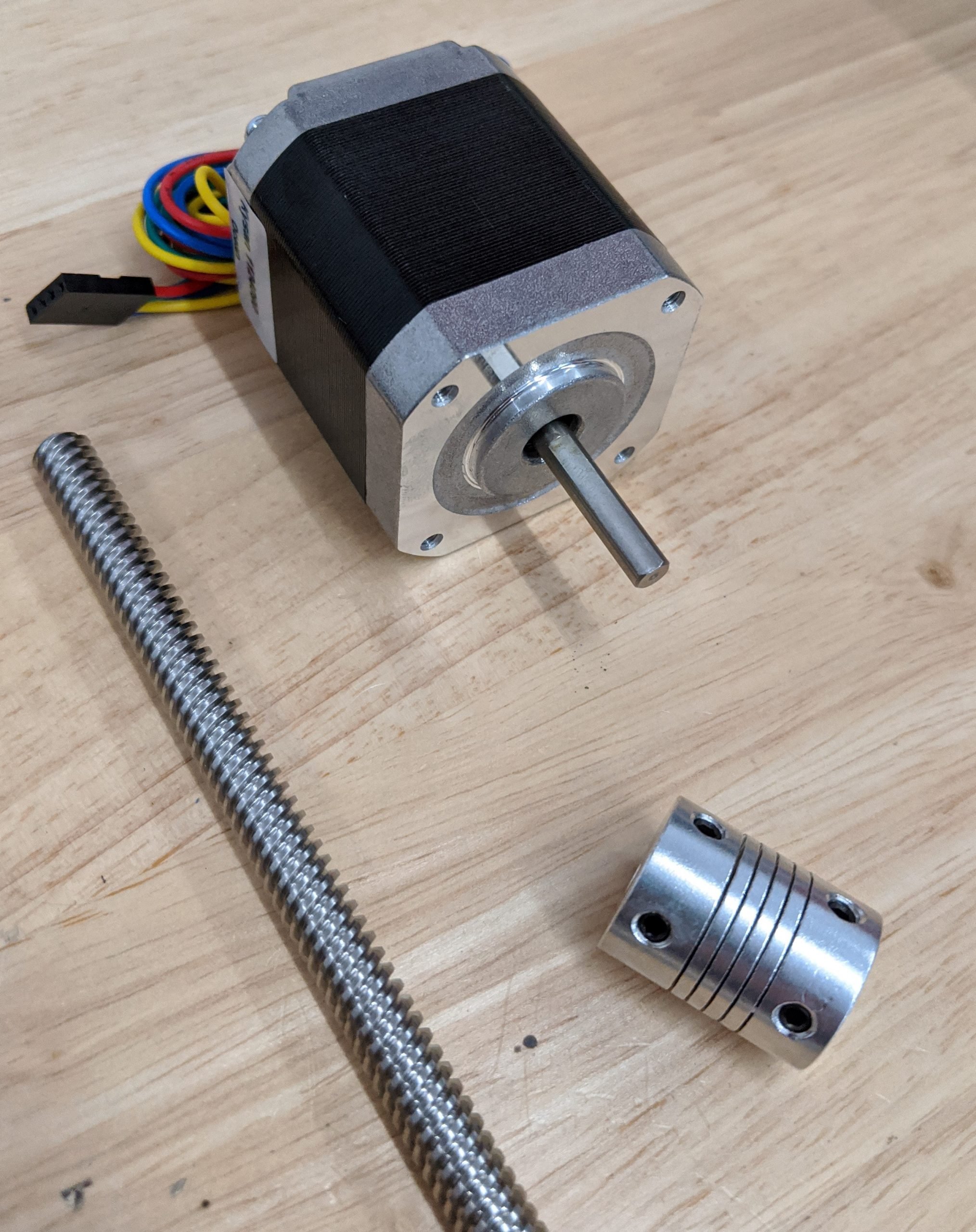
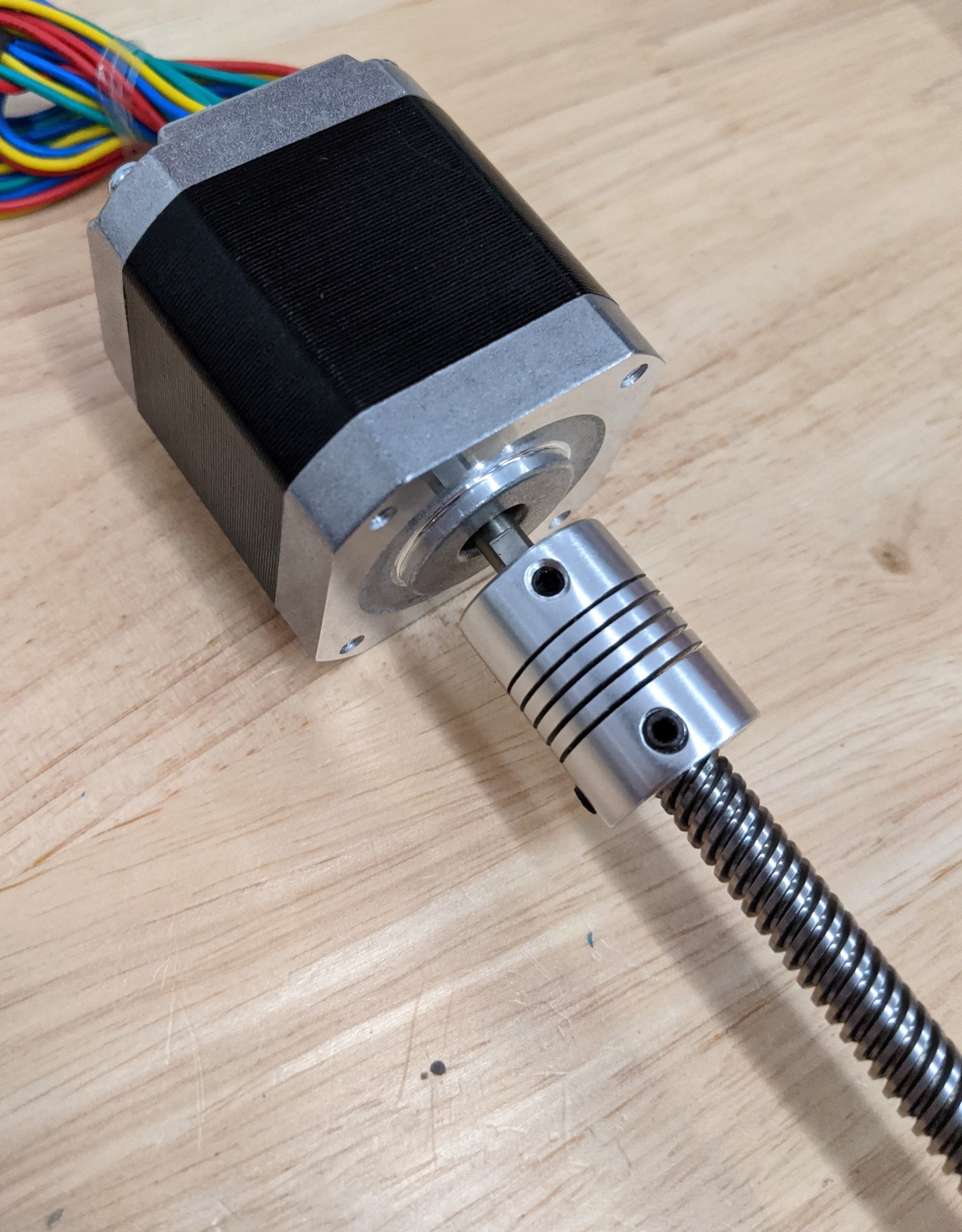
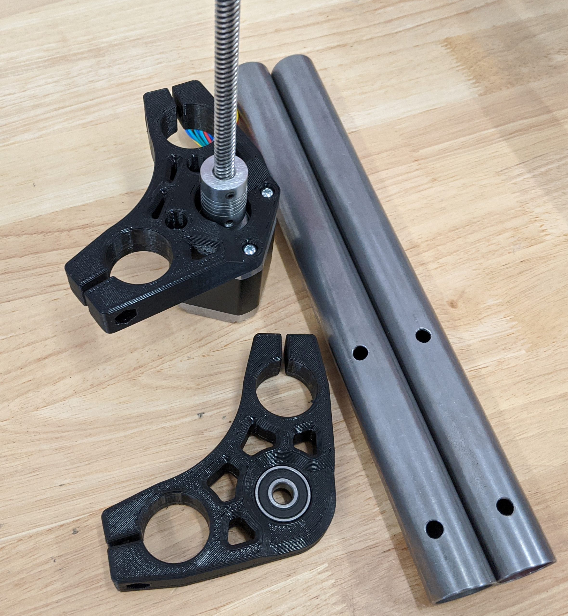
- This step requires a stepper, 5mm to 8mm coupler, and your leadscrew.
Note
The cut calculator gives you a minimum screw length. The maximum screw length is the end of the Z rails when your axis is fully assembled.
- Loctite is a good idea for the small grub screws.
- Tighten the grub screw on the flat spot of the stepper shaft first.
-
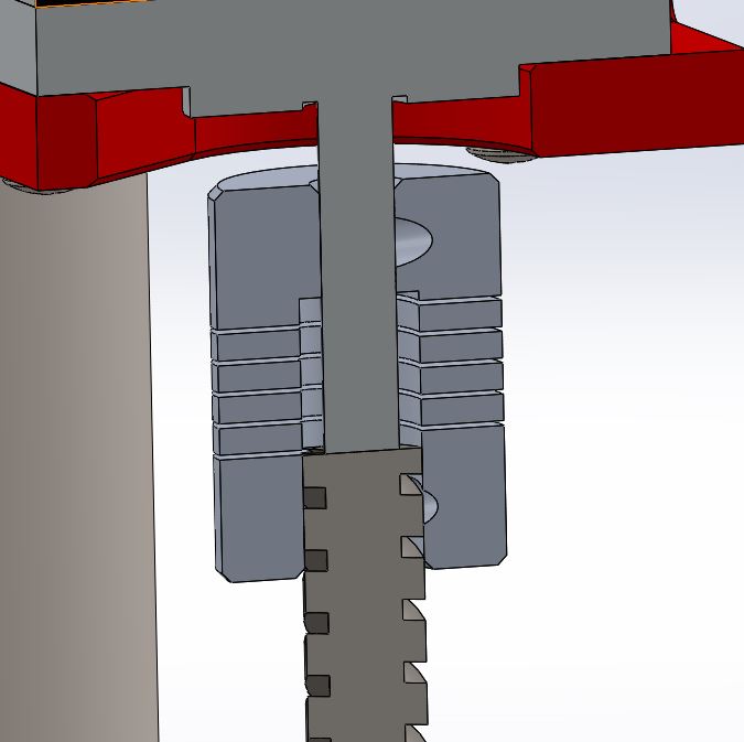
This is how these couplers should be used. The coupler should not be compressed; if anything, a little stretch to make sure the lead screw is in contact with the stepper shaft - this prevents bouncing. The lead screw should only be inserted as far as the coupler bottom collar. This lets the stepper shaft and leadscrew move for any minor misalignment.
-
Seat the grub screws on the shaft trying to get the straightest connection possible. If you hit an edge of a thread it will get wonky; just give it a little turn and try again. On the stepper shaft, tighten the flat screw first then the one that hits the round surface.
Stepper
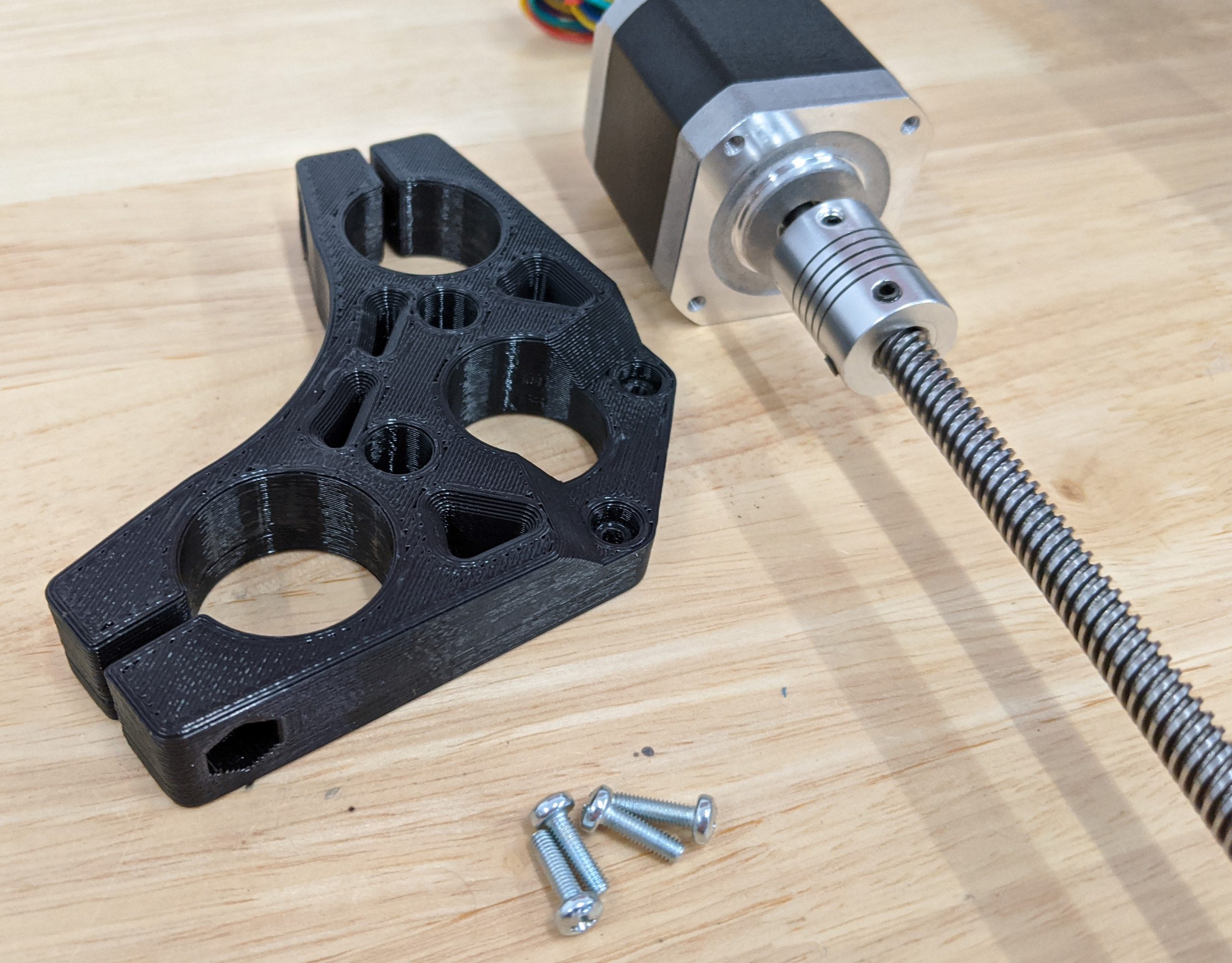
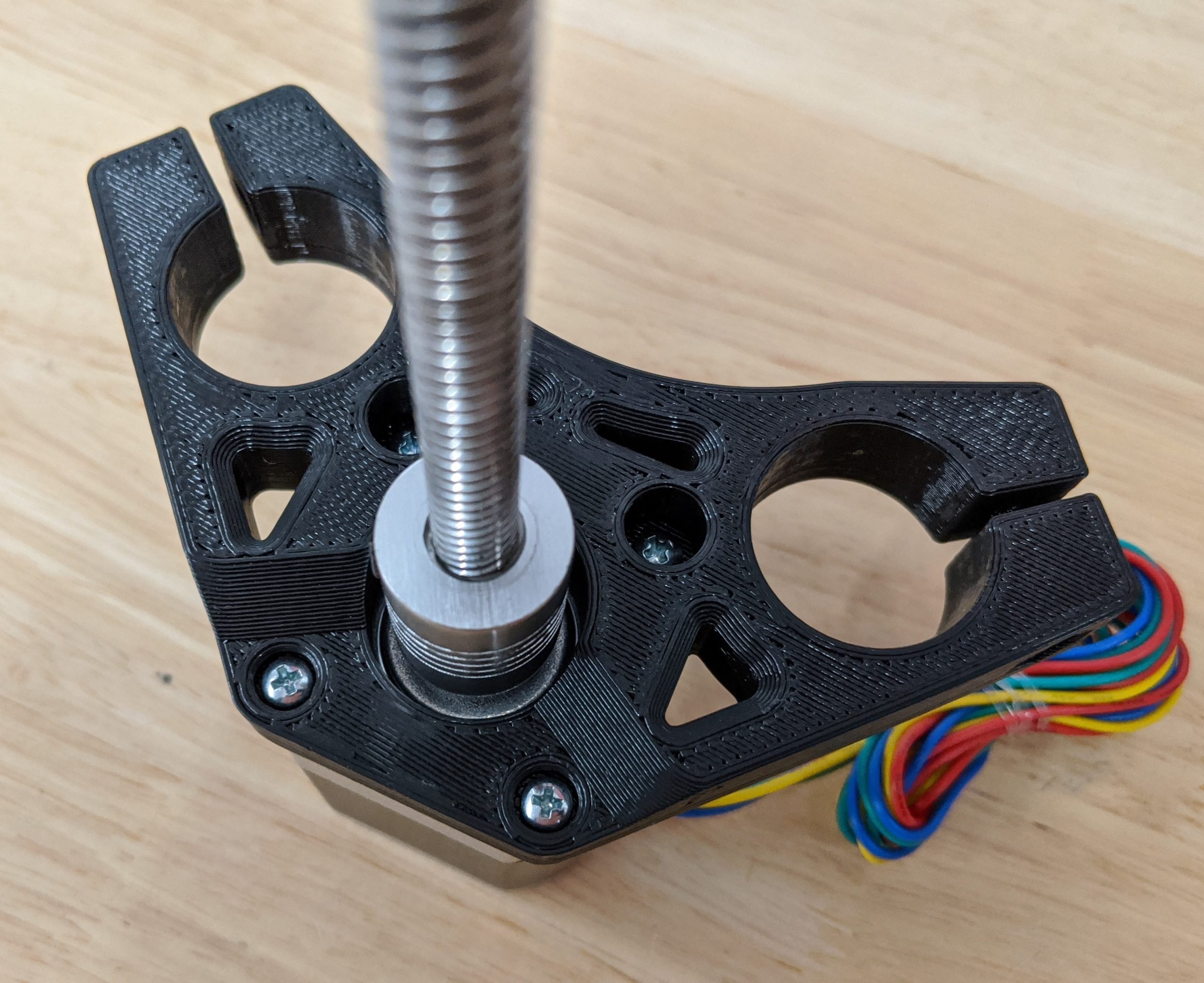
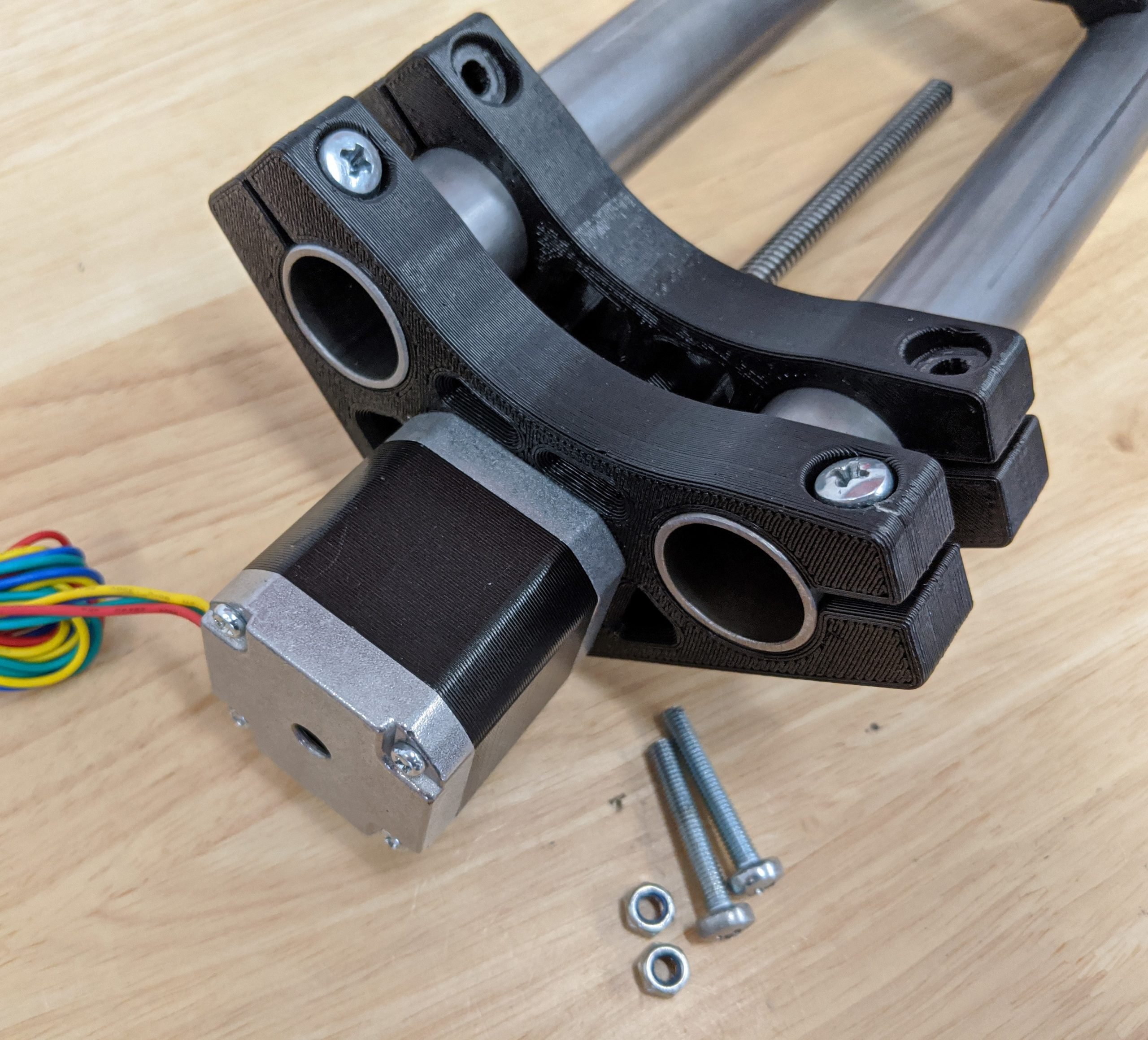
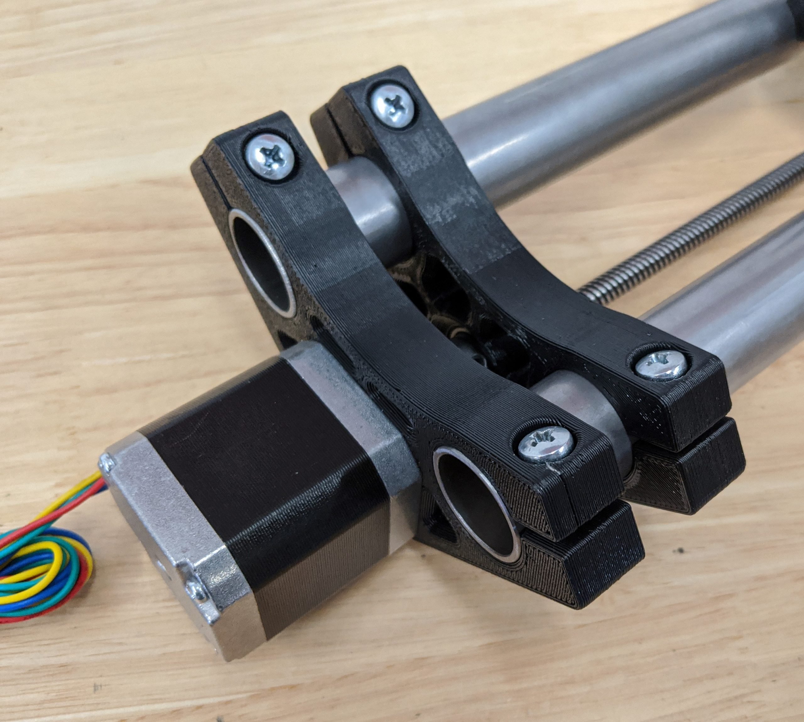
- This step uses 4 M3x10mm screws, the printed Z Motor part, and the previous leadscrew assembly.
- Snug down all 4 screws.
- These stepper screws are easy to cross thread, take it slow and do not force anything.
Thrust Block
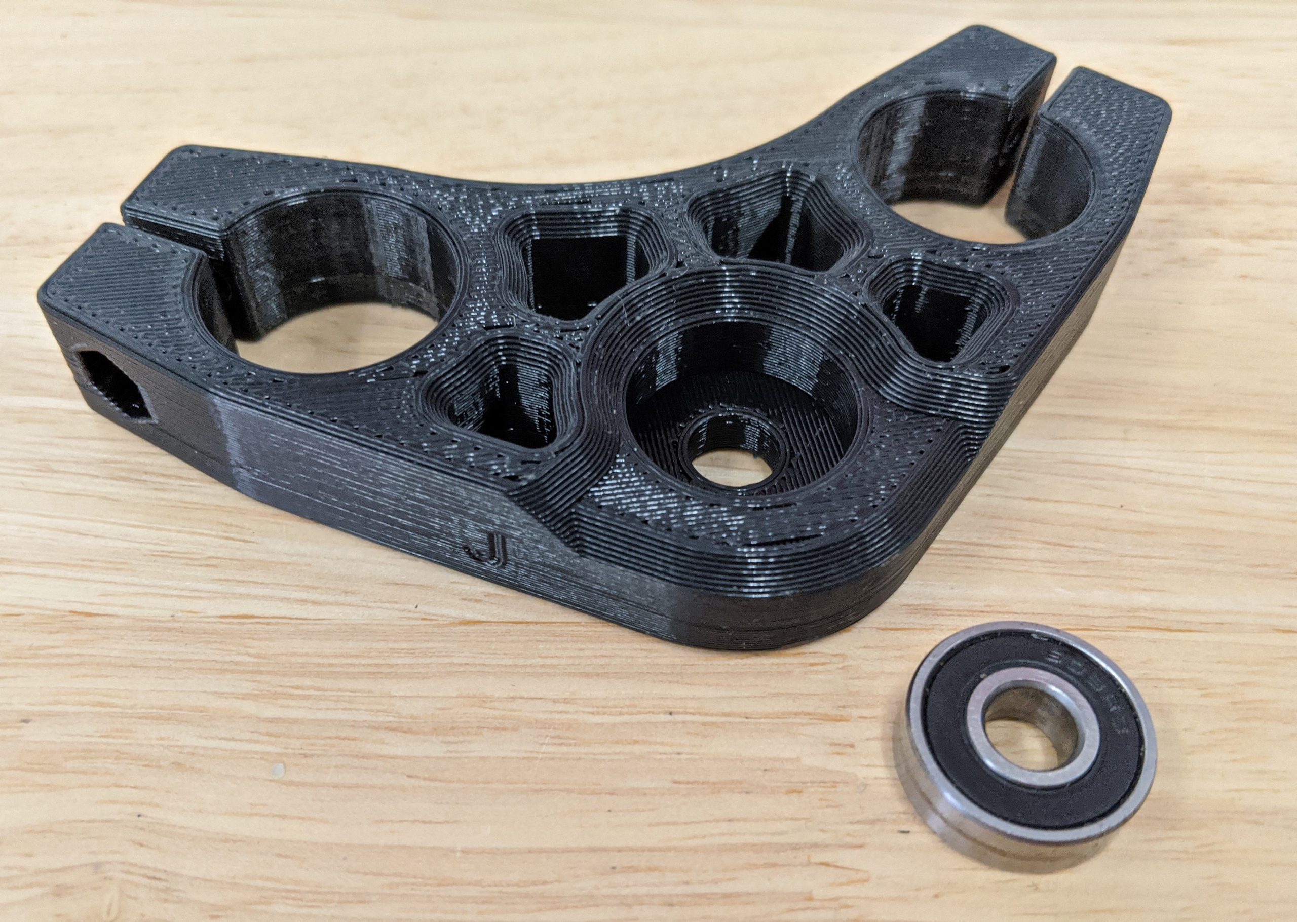
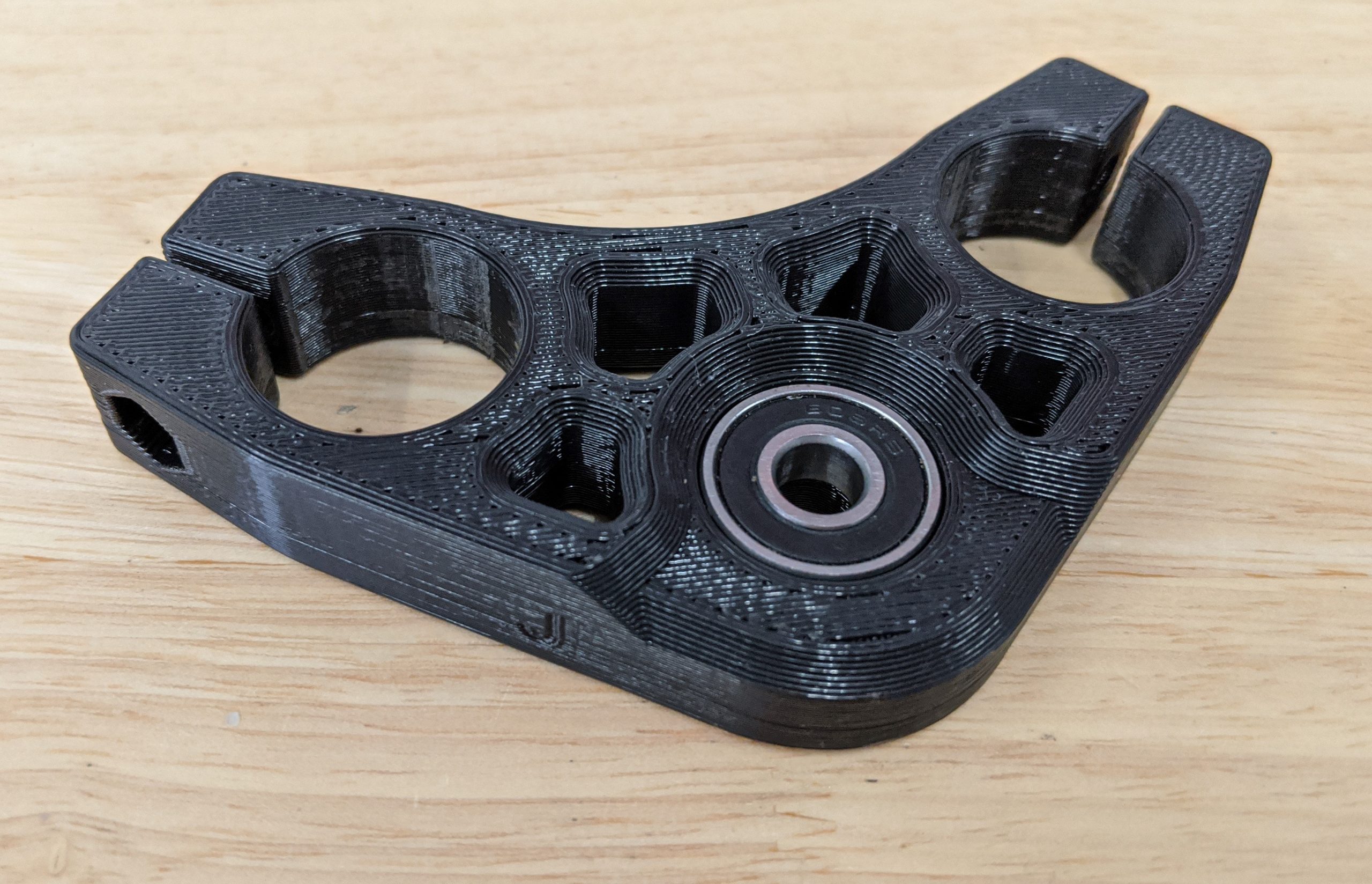
- All you need is a bearing and the printed Z Coupler part for this step.
- Seat the bearing - the top should be flush with the part.
Z Axis
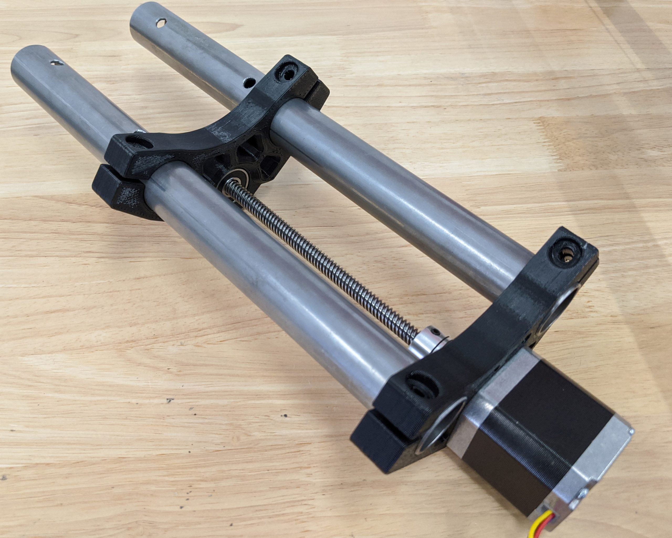
- You will need all of the previous assemblies from this step.
- Pay attention to the direction the Z Coupler part is facing. Face the bearing towards the coupler. They will end up touching.
- Slide both rails in. The holes you drilled angle in and are on the same end.
Info
The lower Z Coupler part stays just above the middle holes to help with alignment. Don’t push it all together yet.
- The stepper assembly should be flush with the top of the Z rails.
Note
The leadscrew can be a tight fit through the bearing. If this is the case, you can sand the top 30mm or so of the leadscrew and put the bearing on before the coupler.
Nut Traps
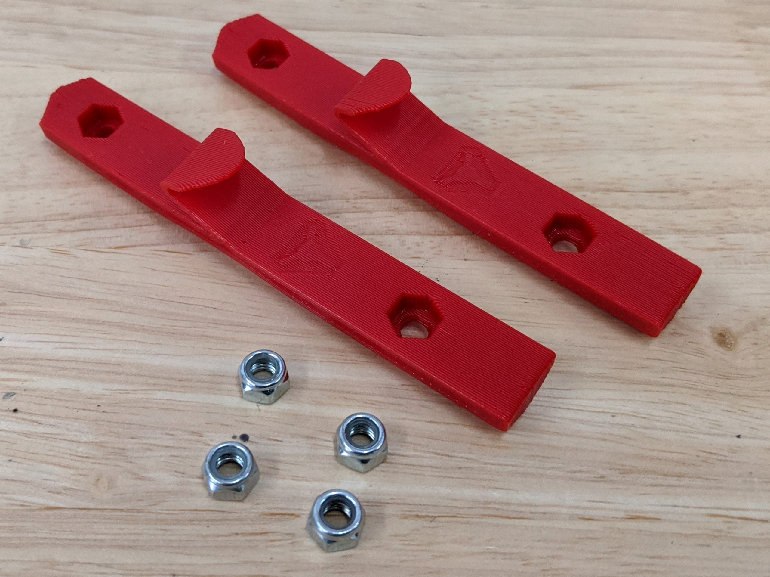
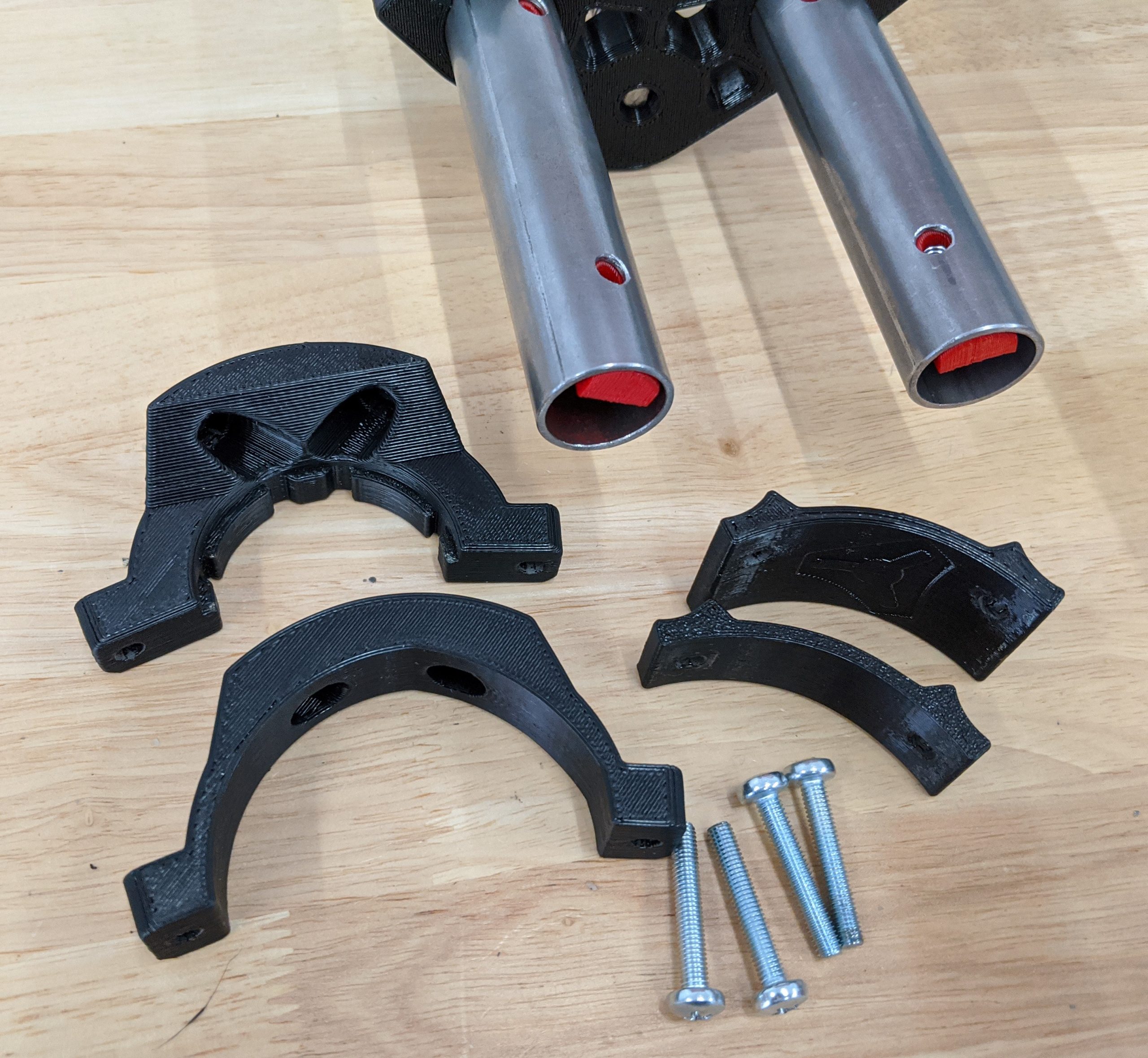
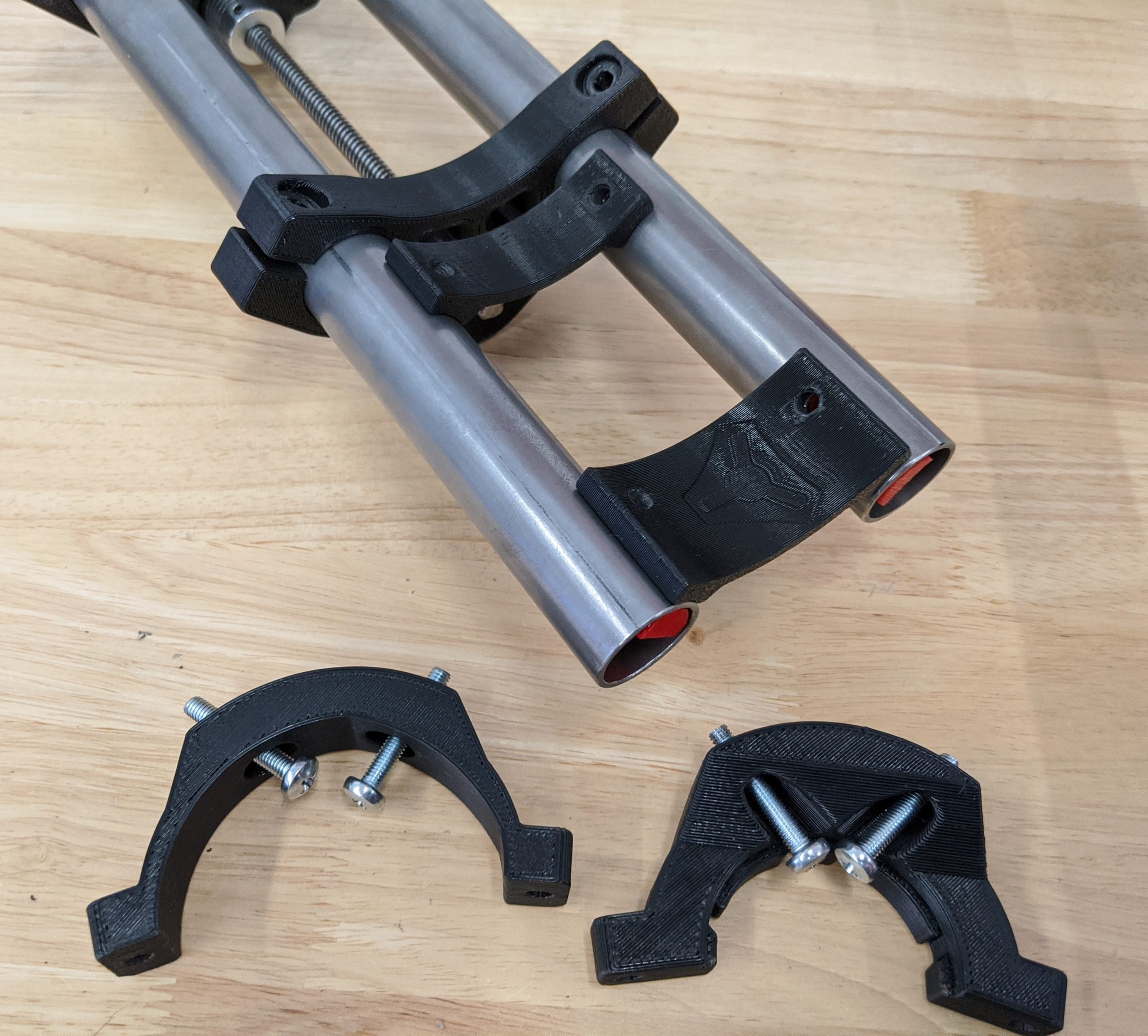
- You will need the printed Nut Trap parts, and four M5 nuts.
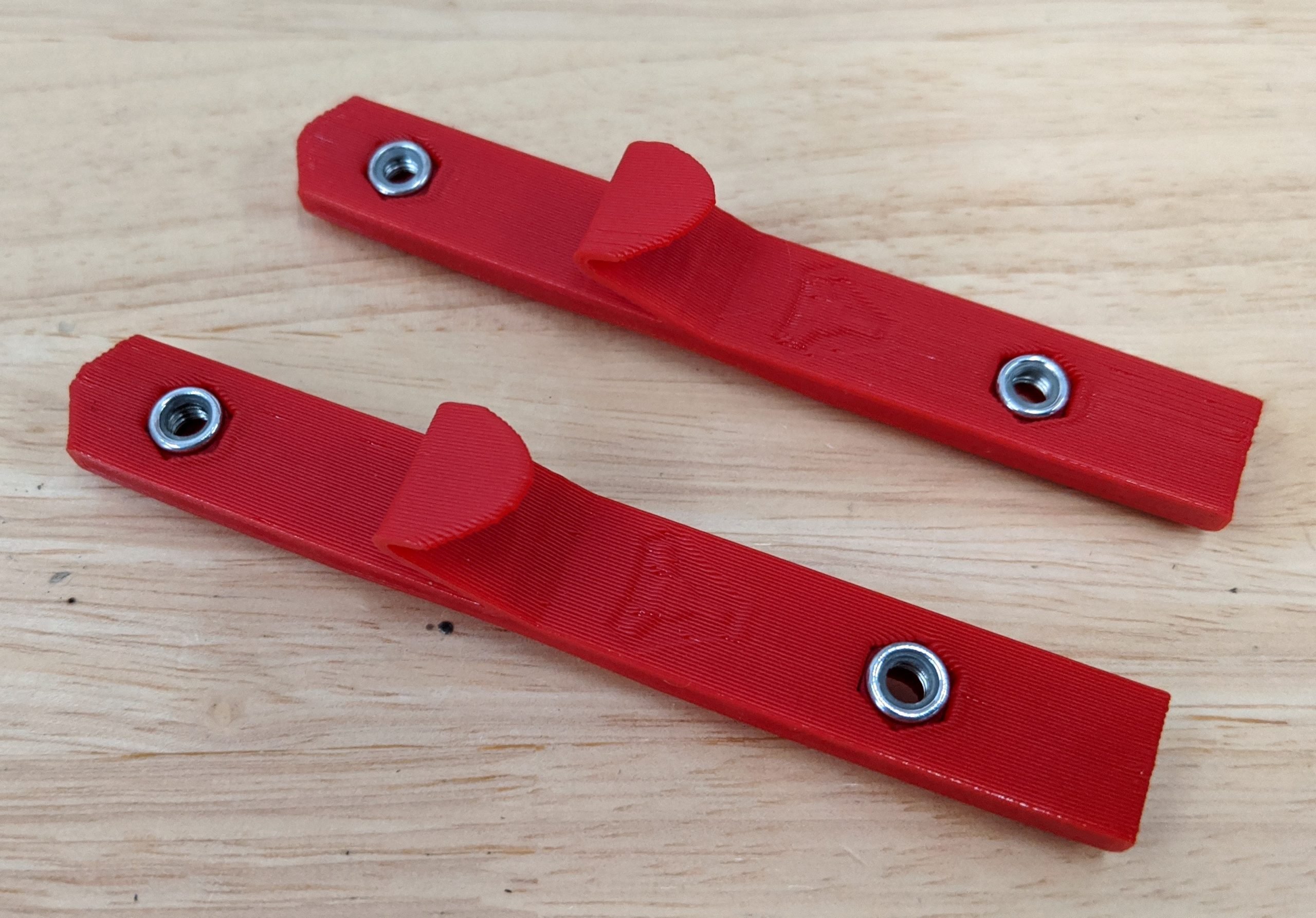
- Pay attention to the direction the nylocks are facing.
- If you haven’t already, it’s highly recommended to pre-thread the nuts here.
- Seat the nuts in fully.
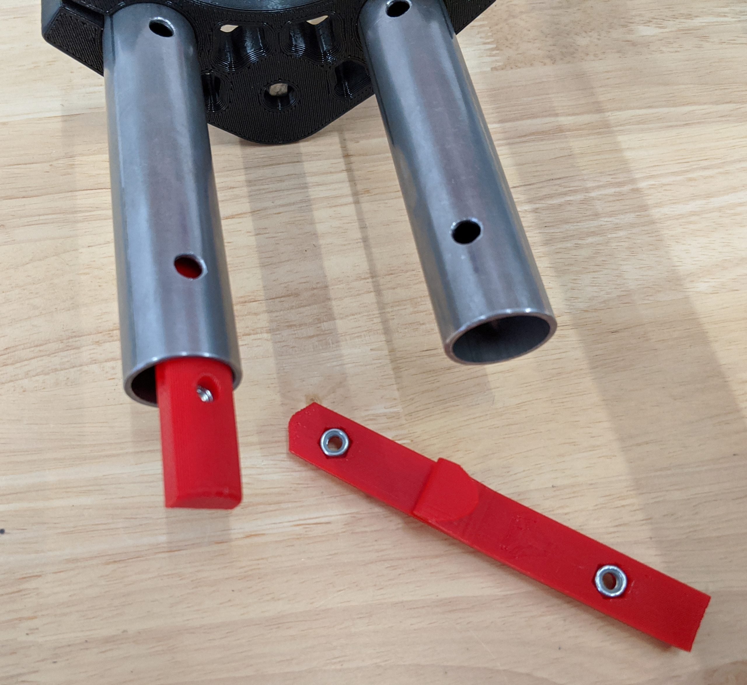
- A drop of glue is a good idea here. These are blind nuts and that prevents them from getting pushed out.
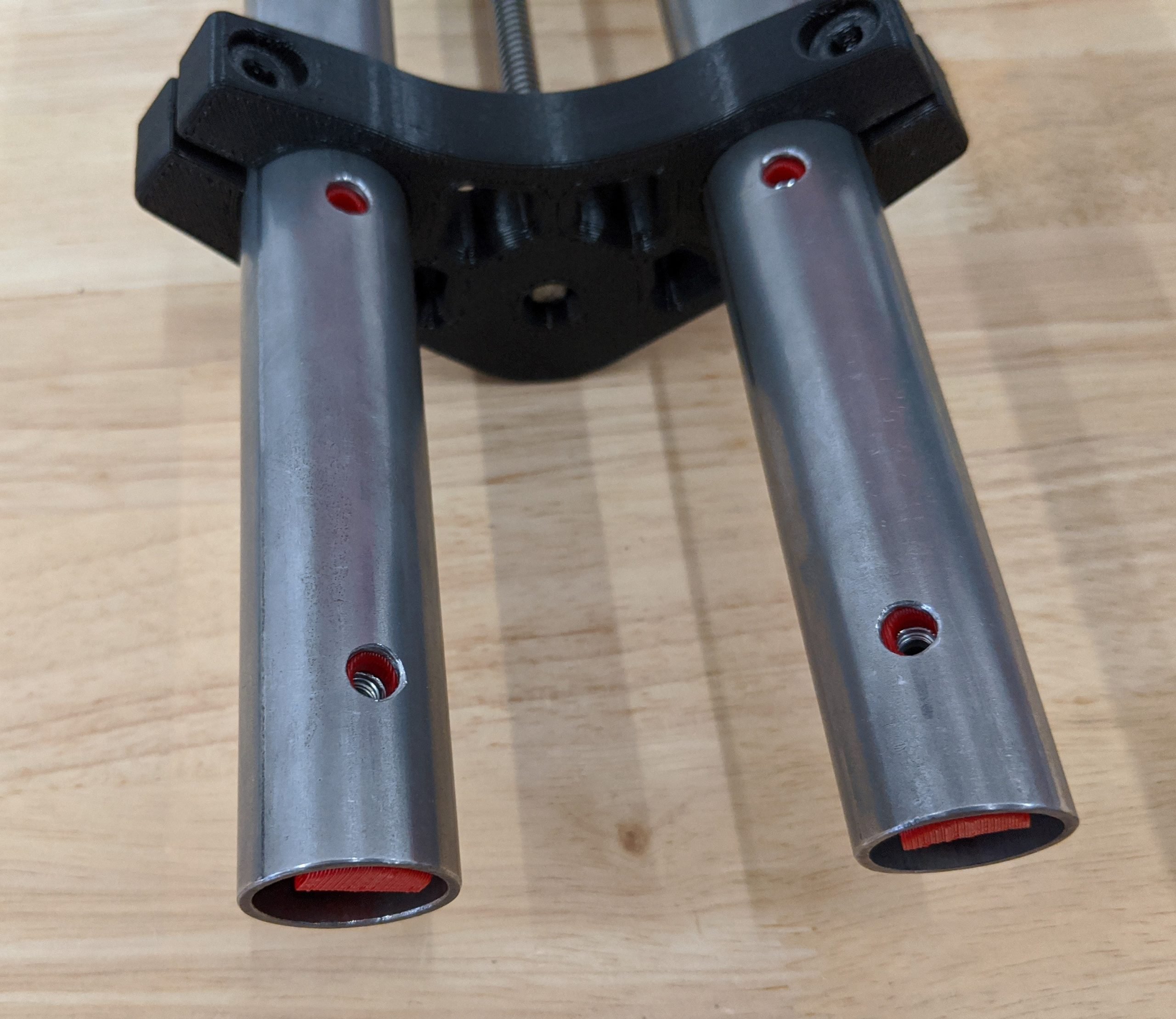
- Slide the Nut Traps into the rails. Pointy end first.
- The bottoms of the Nut Traps should be flush with the bottoms of the Z rails and the holes aligned.
Tool Mount
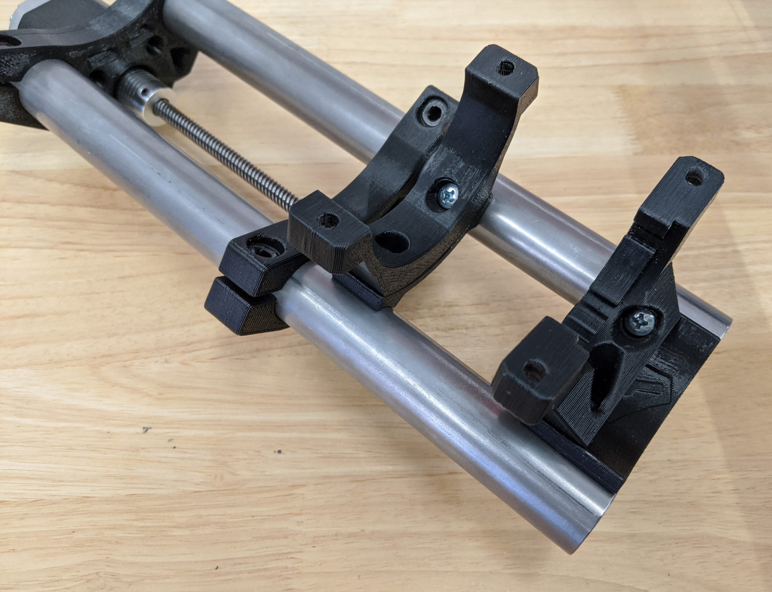
- For this step you will need your tool mount of choice, 2-4 M5 screws depending on the mount, and both Upper and Lower printed Tool Plates.
- This is showing the Dewalt 660 mount.
- Using the embossed part letter as your guide position the plates.
- For this mount it is easy to start the screws and then loosely fit both tool mount pieces and get the screw well into the nuts.
- Once all four screws are started you can tighten them all a little at a time to keep the rails aligned.
- Snug these up all the way.
- You can now slide the Z Coupler part up to the coupler.
- The bearing should make contact with the coupler; it prevents the coupler stretching.
- Snug up the stepper assembly to the Z rails.
Warning
These are clamping parts so there will be a gap even when the part is tight.
- Very little force is needed here; 4 screws have a lot of holding power and they are only holding a few pounds.
- Push the bearing plate up to the coupler and make sure they are touching.
- The plates should be parallel and have equal spacing on both sides.
- Snug up the plate.
Warning
You can get the plate too tight and make the leadscrew hard to rotate. Once you have finished this step, make sure the coupler moves easily with your fingers.
Z Core
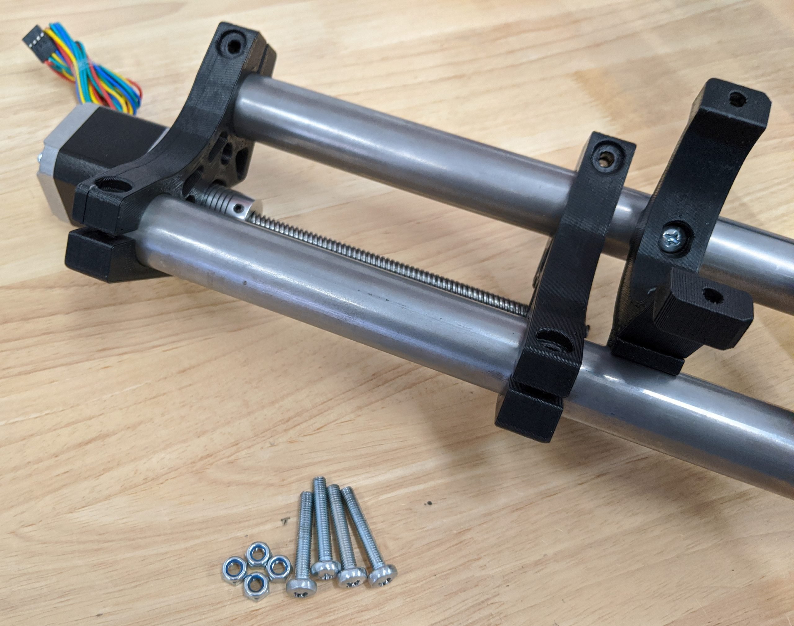
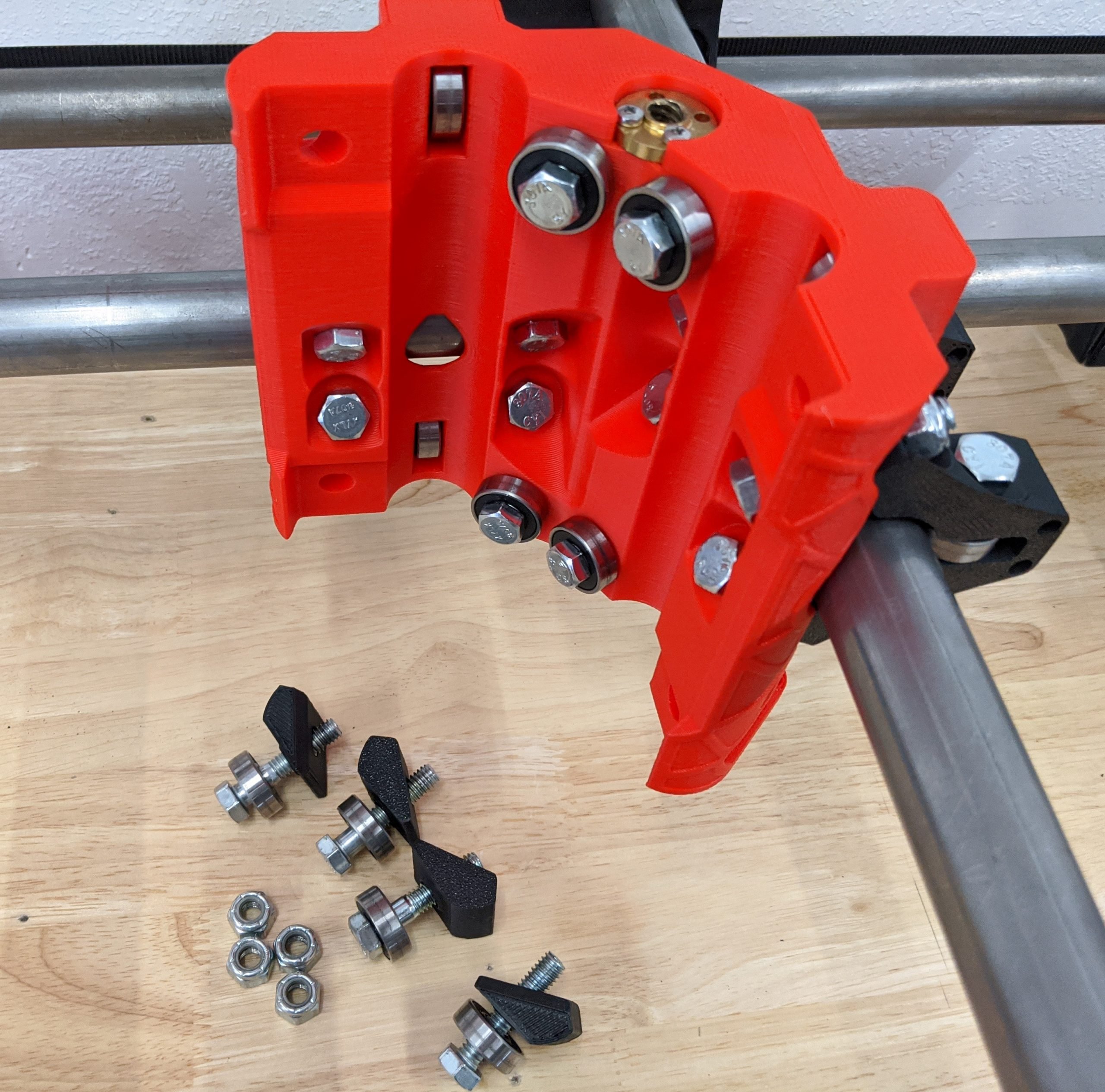
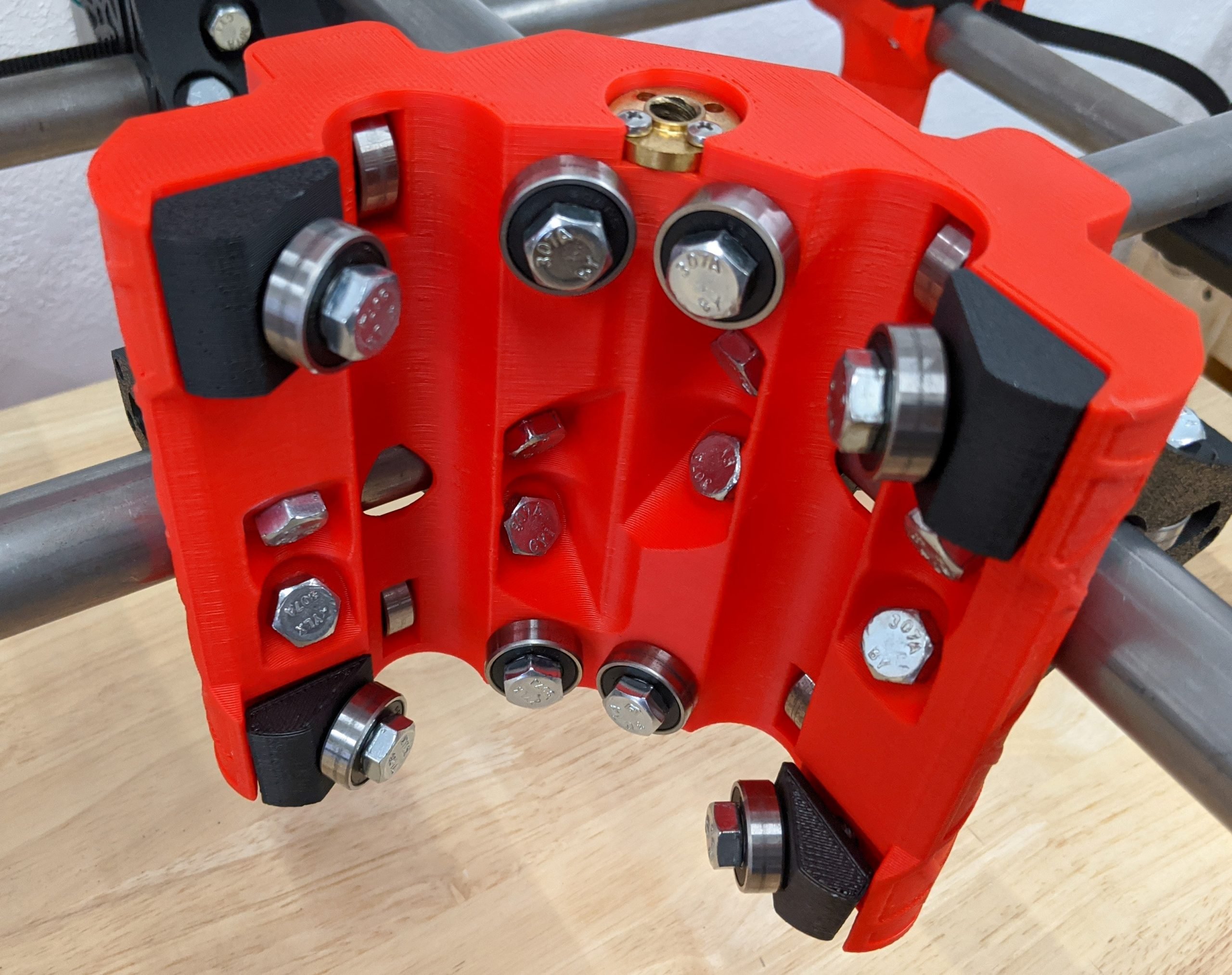
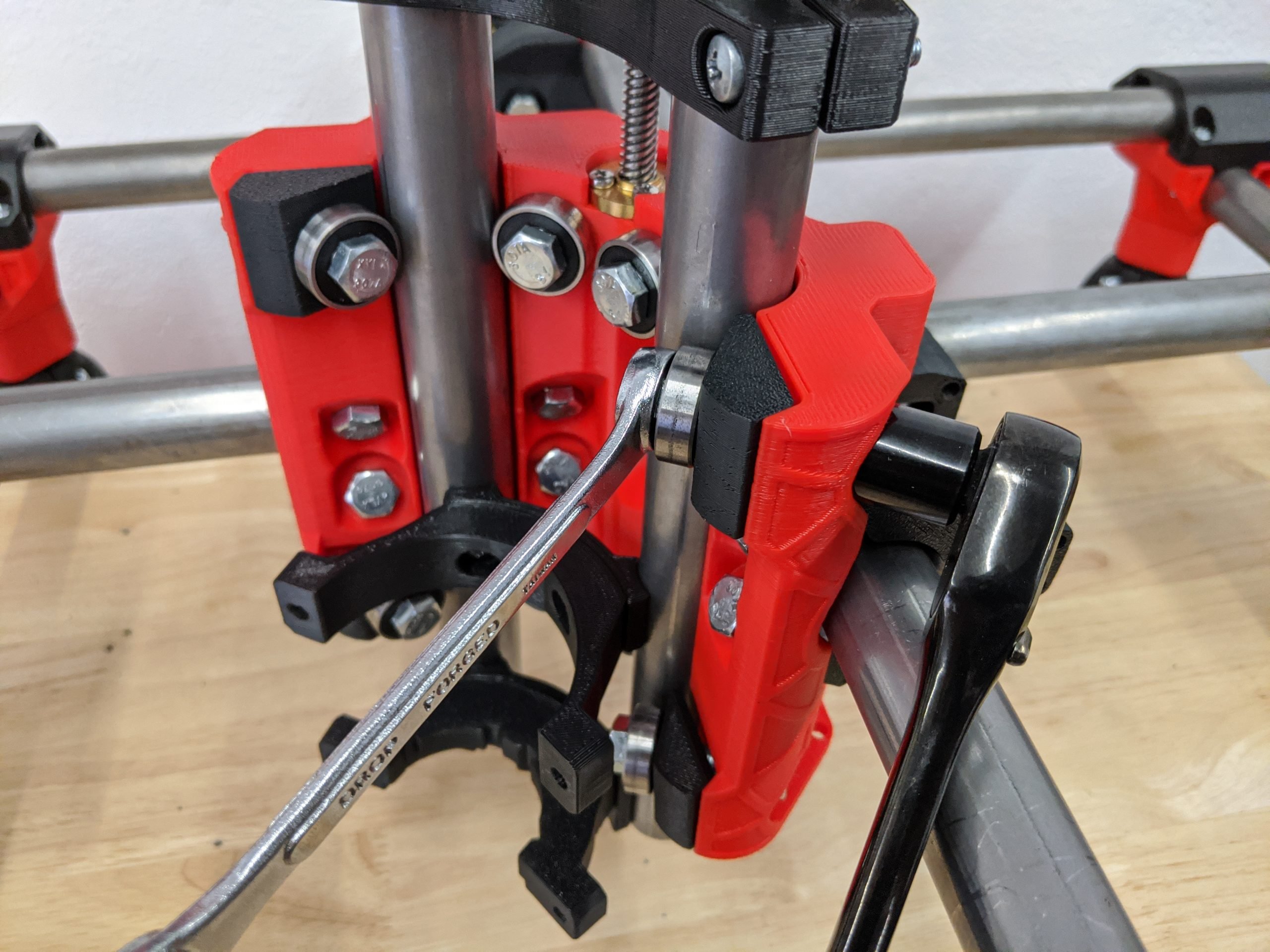
- For this step you will need 4 nuts, bolts, bearings, and all four Core Z Clamp printed parts.
- The Core Z Clamps have an angled edge that should match the angled edge on the Core itself.
Warning
These bolts need to be extremely loose, only turn to just get the nylocks engaged.
- Insert the Z axis and get the leadscrew started to hold it in place.
- Very carefully start to tighten each clamp.
- You want each bearing to be in contact with the rail, but you should just be able to rotate the bearing with your fingers.
- 1/16th of a turn here can be drastic. Take your time.
- You want each bearing to be in equal tension. This flexes the Core properly and keeps the Z axis perpendicular to the work surface.
- Over tightening is detrimental. Again, loose is better than tight.
- Move the axis up and down and check for free movement through the entire range.
Tip
You can give the Clamps a little tap to make sure they are seated correctly once they have some tension on them. Recheck the tension in the bearings.
Note
If your leadscrew starts to bind at the very bottom this is when you can move the brass nut screws around a bit to make sure this has smooth easy movements.
Lubricate the Leadscrew
The leadscrew needs lubrication.
Nice work....Break time?
