Base
Click on the images to embiggen.
Feet
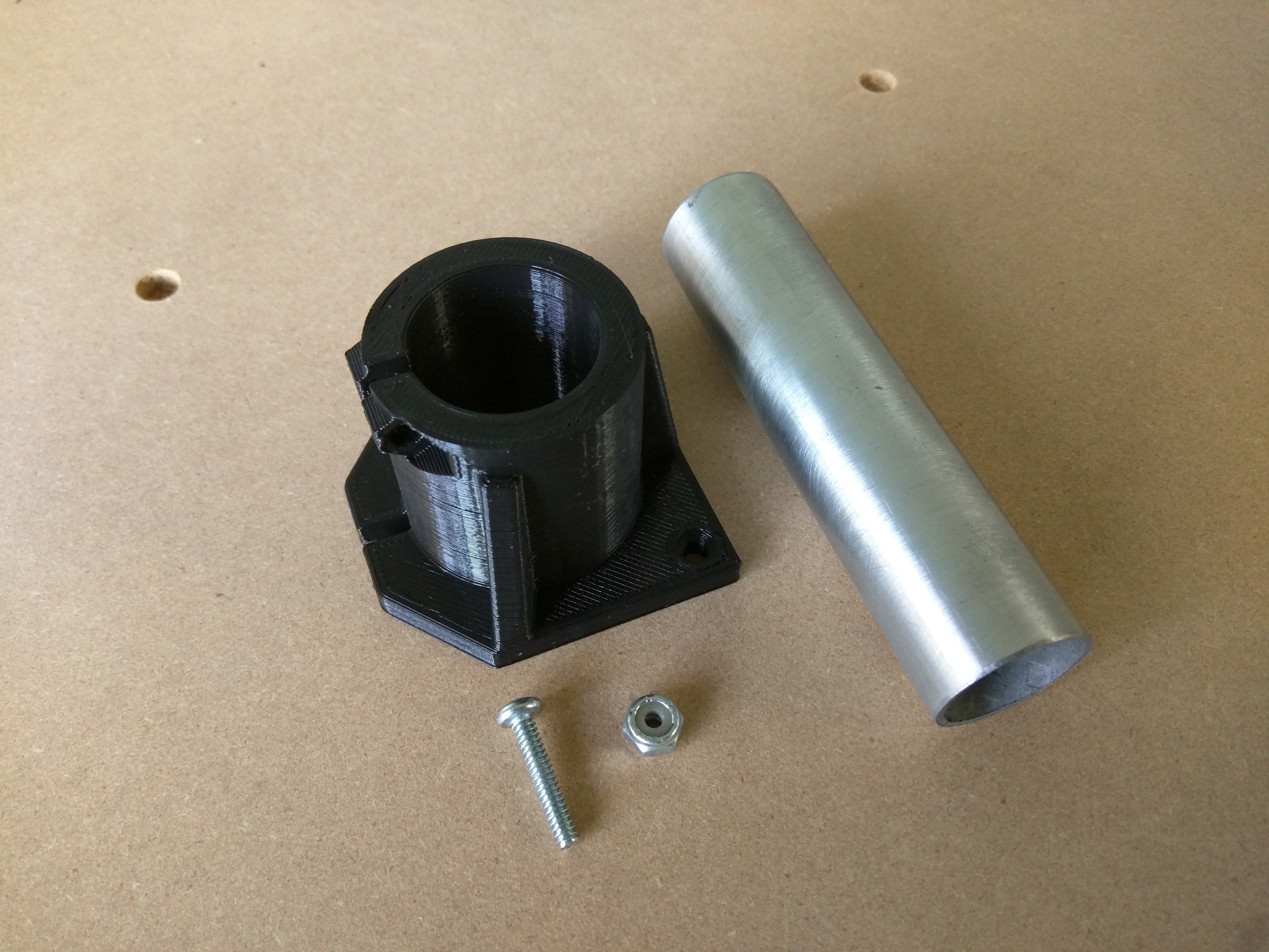
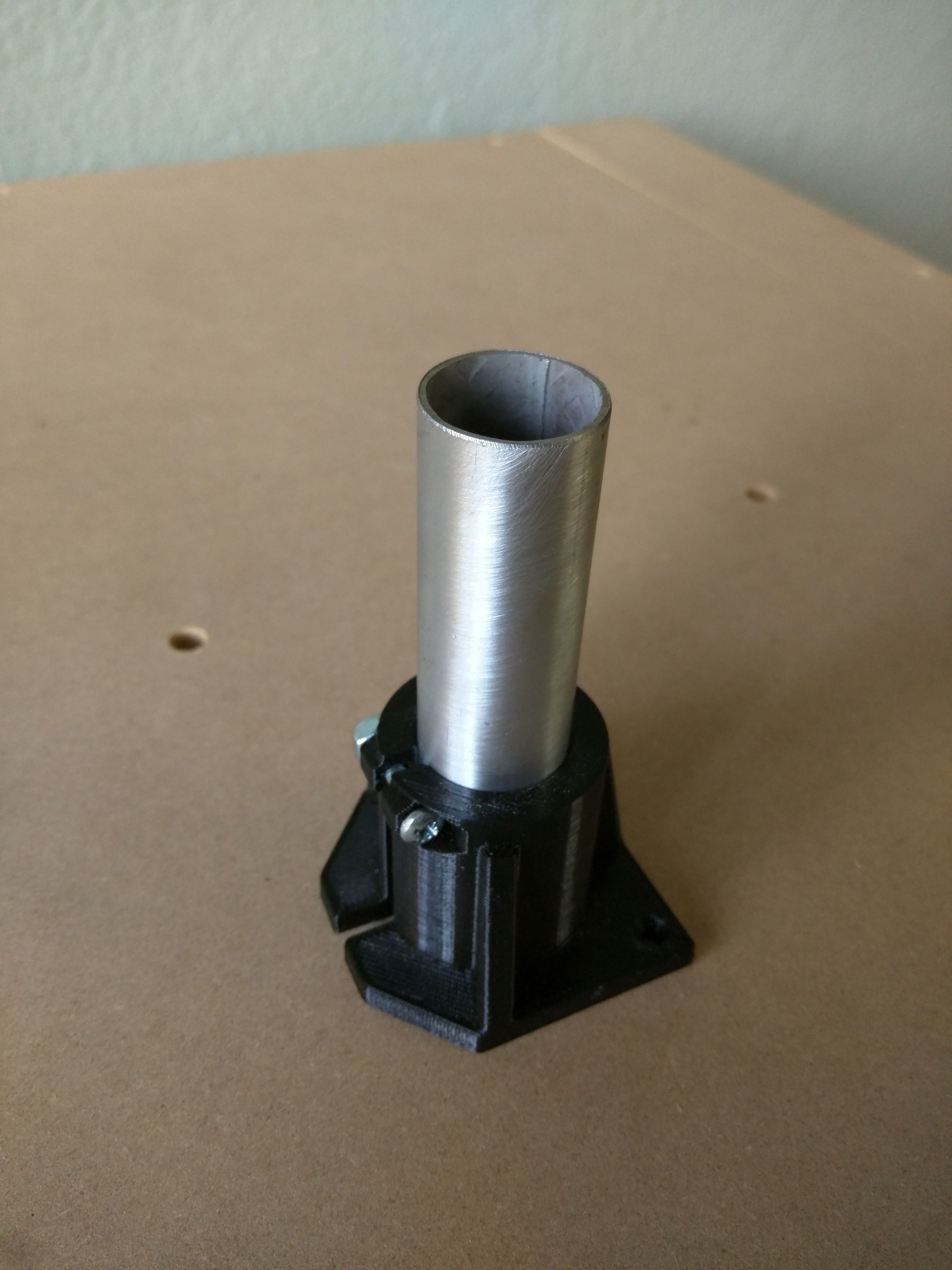
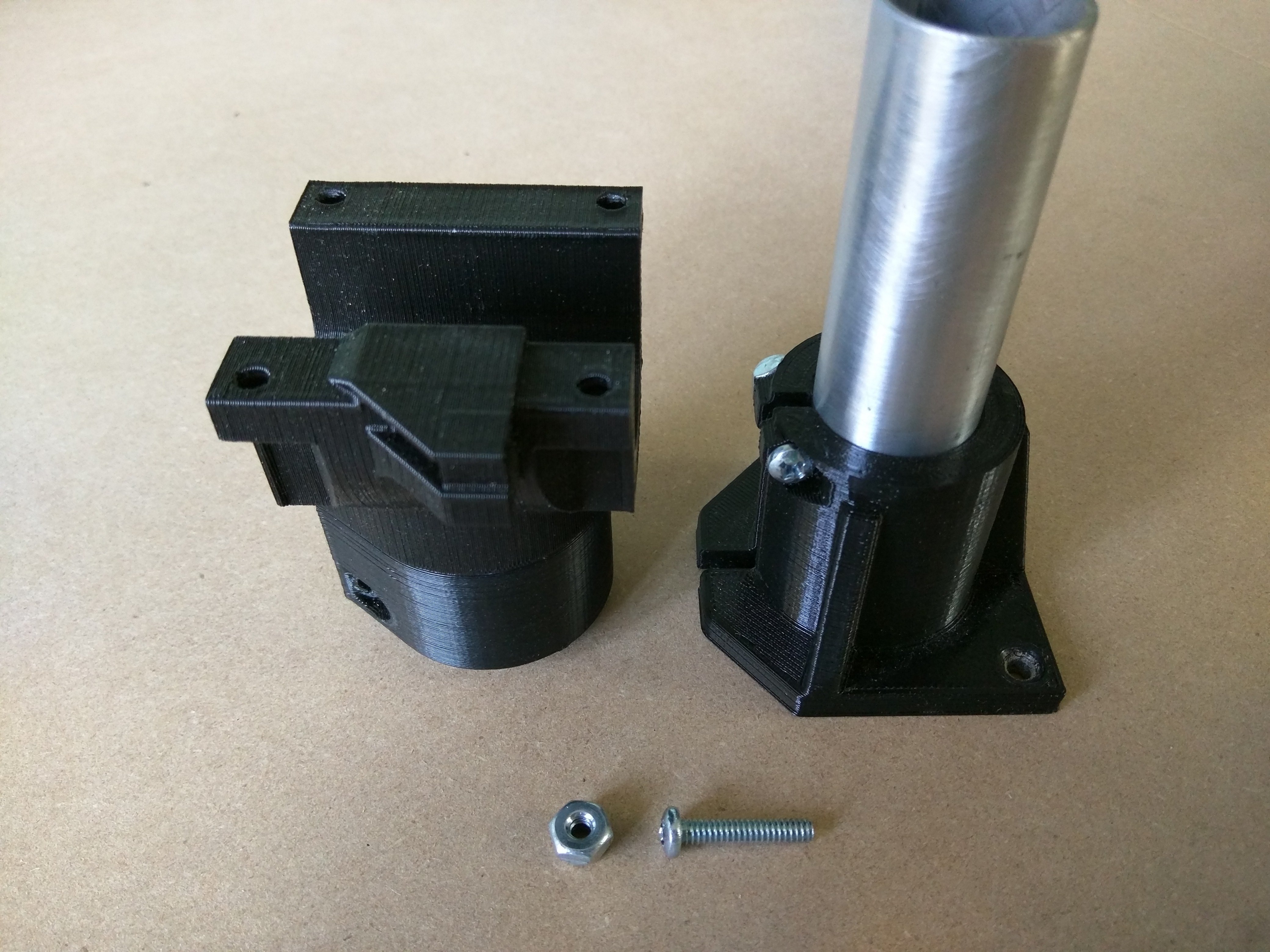
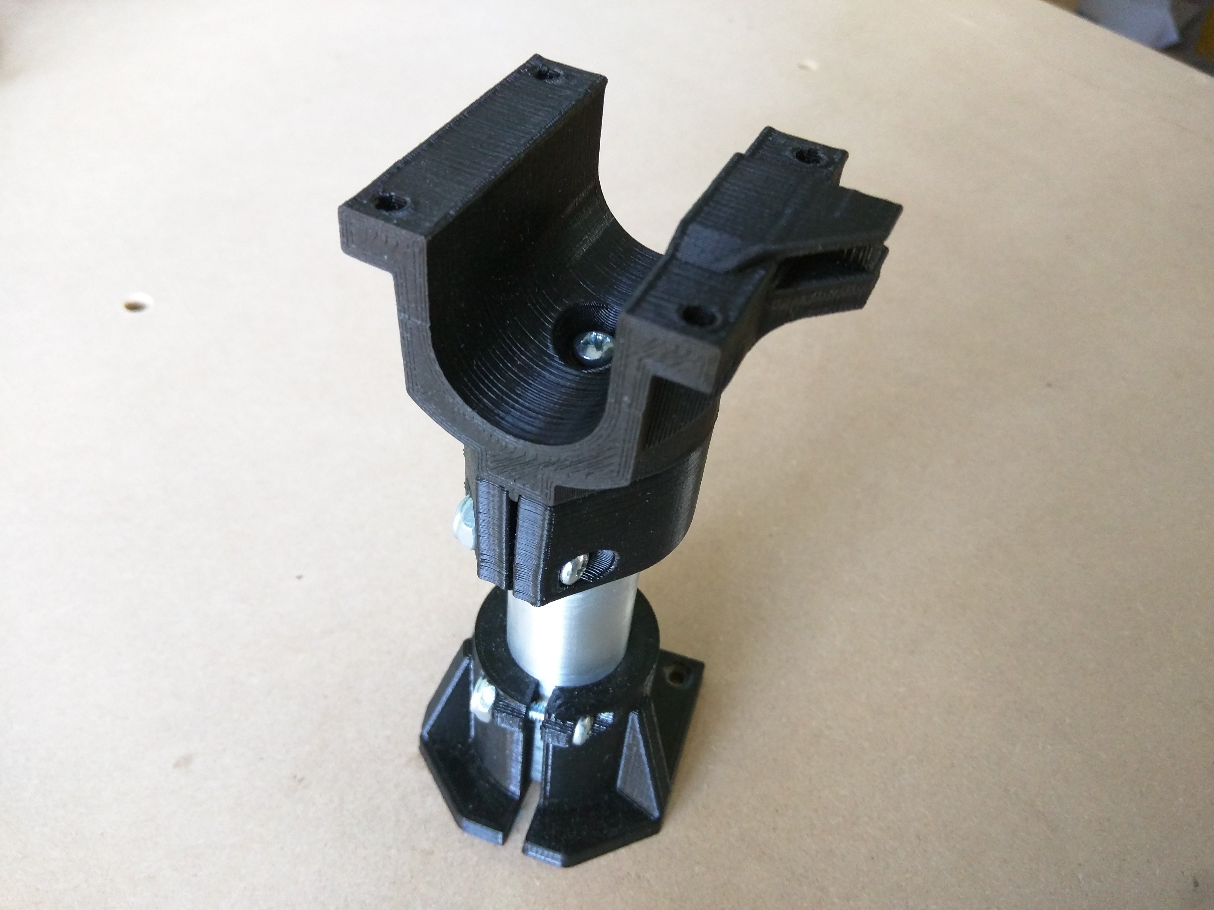
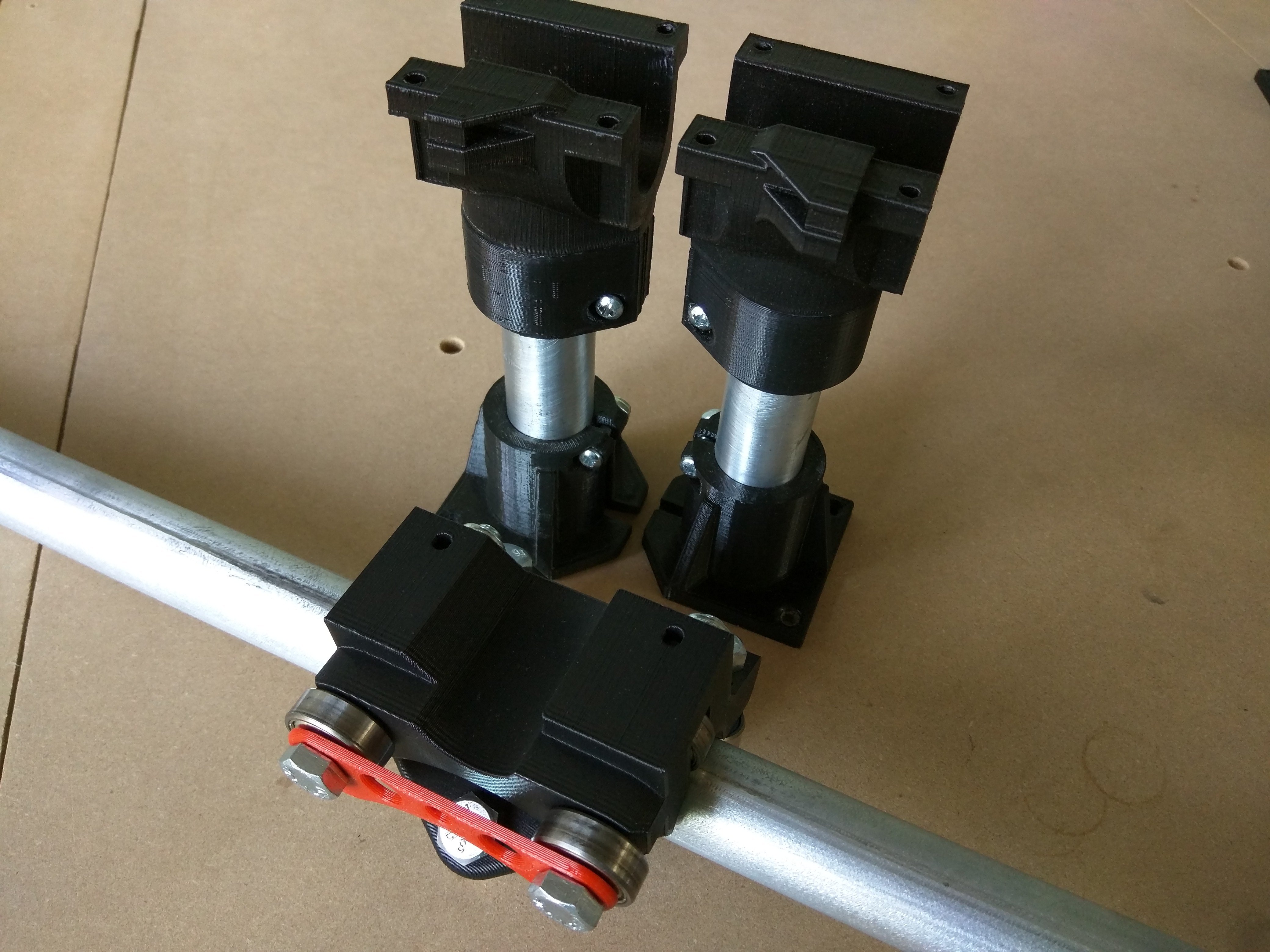
- ¾″ (M4 X 20), *-Foot_2018, screw and lock nut, leg rail.
- Insert the previously cut Leg into the Foot Bottom and loosely add the ¾″ (M4 X 20) screw and lock nut. This will get tightened during the final step.
Bottom Corner and Lock Corner
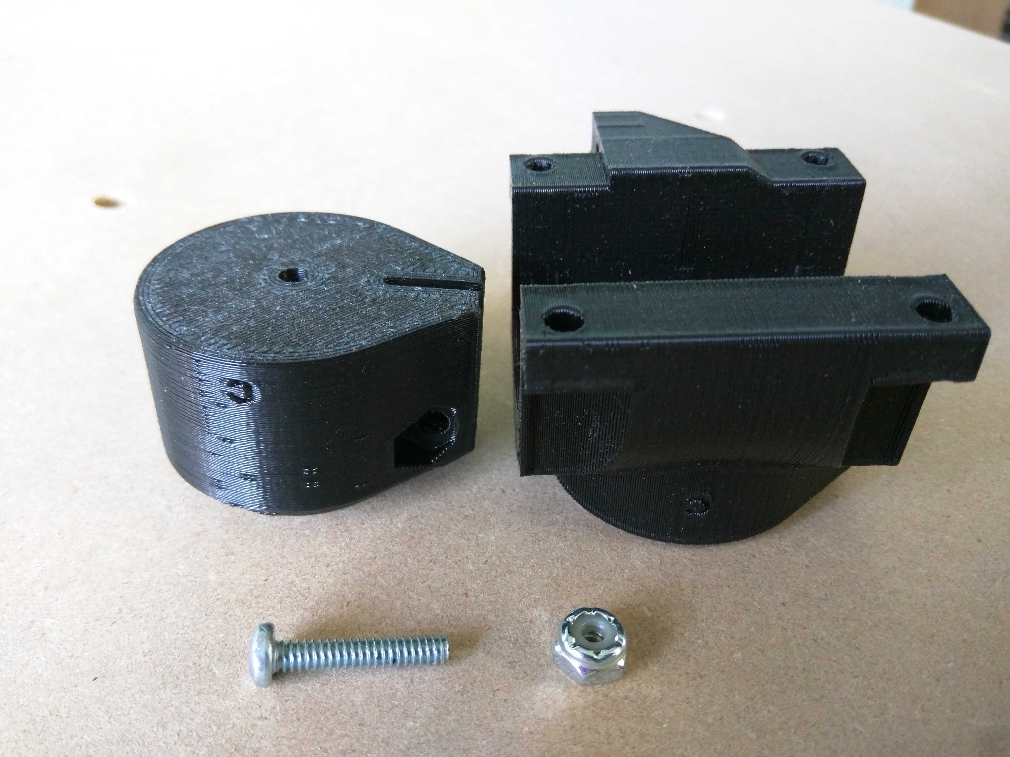
- Bottom_Corner and Lock_Corner parts or BottomM_Corner and LockM_Corner, ¾″ (M4 X 20) Scew and nut, optional Cyanoacrylate Glue.
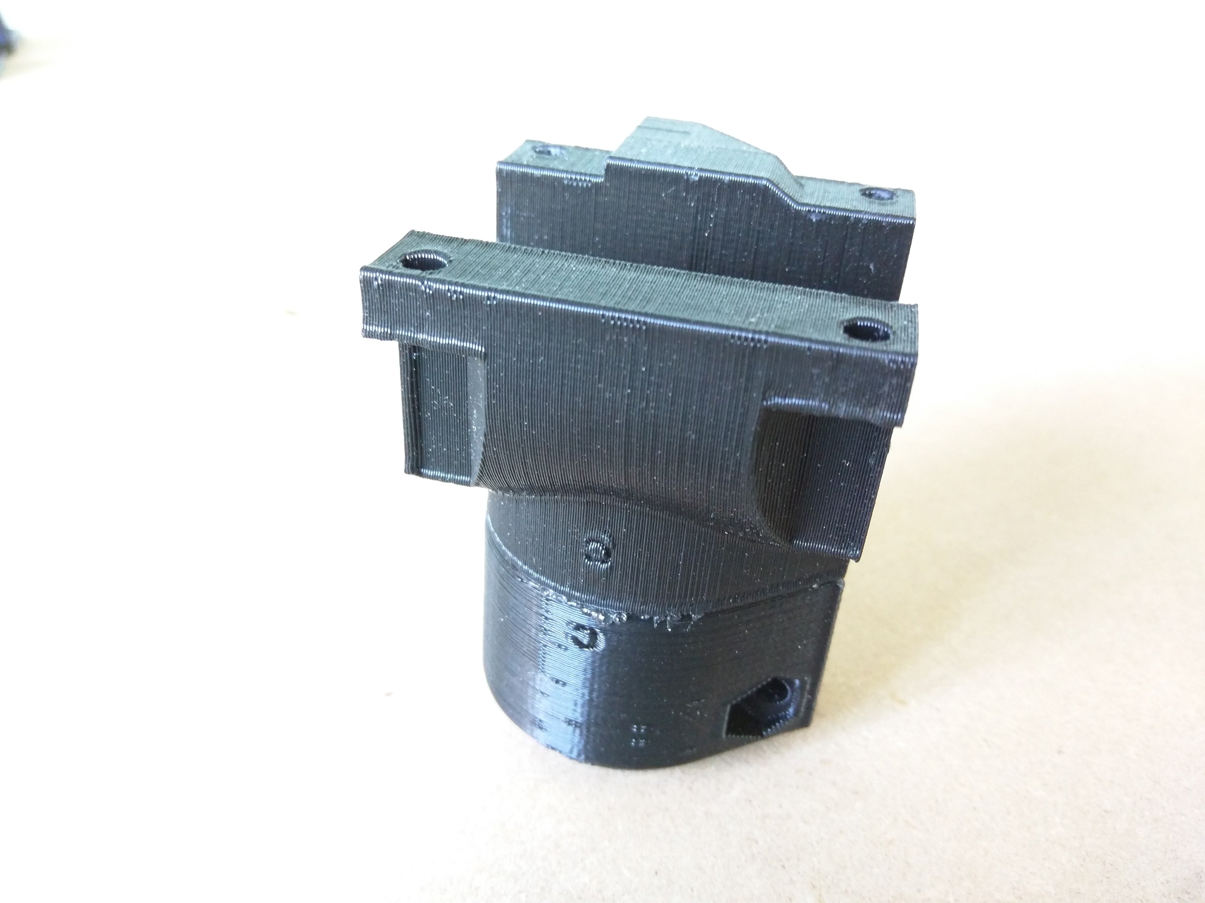
- Use the matching Bottom_Corner and Lock_Corner parts or BottomM_Corner and LockM_Corner parts. The direction of the letter will match when assembled of the correct set.
- Optional but suggested, add some glue to these parts before screwing together for added rigidity.
- Put the screw ¾″ (M4 X 20) in from the corner piece and the nut into the lock and hold with a socket or pliers. This screw can get snugged down.
Leg Assembly
- ¾″ (M4 X 20) screw and nut, previous assemblies.
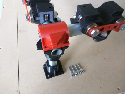
- Assemble the corners on to the Bottoms, add the screw ¾″ (M4 X 20) and nut (nut goes in the hex shaped hole).
- Leave these screws loose, they will get snugged up in the final step.
- Repeat this for all four sets.
Roller Assembly - Fixed Bearings
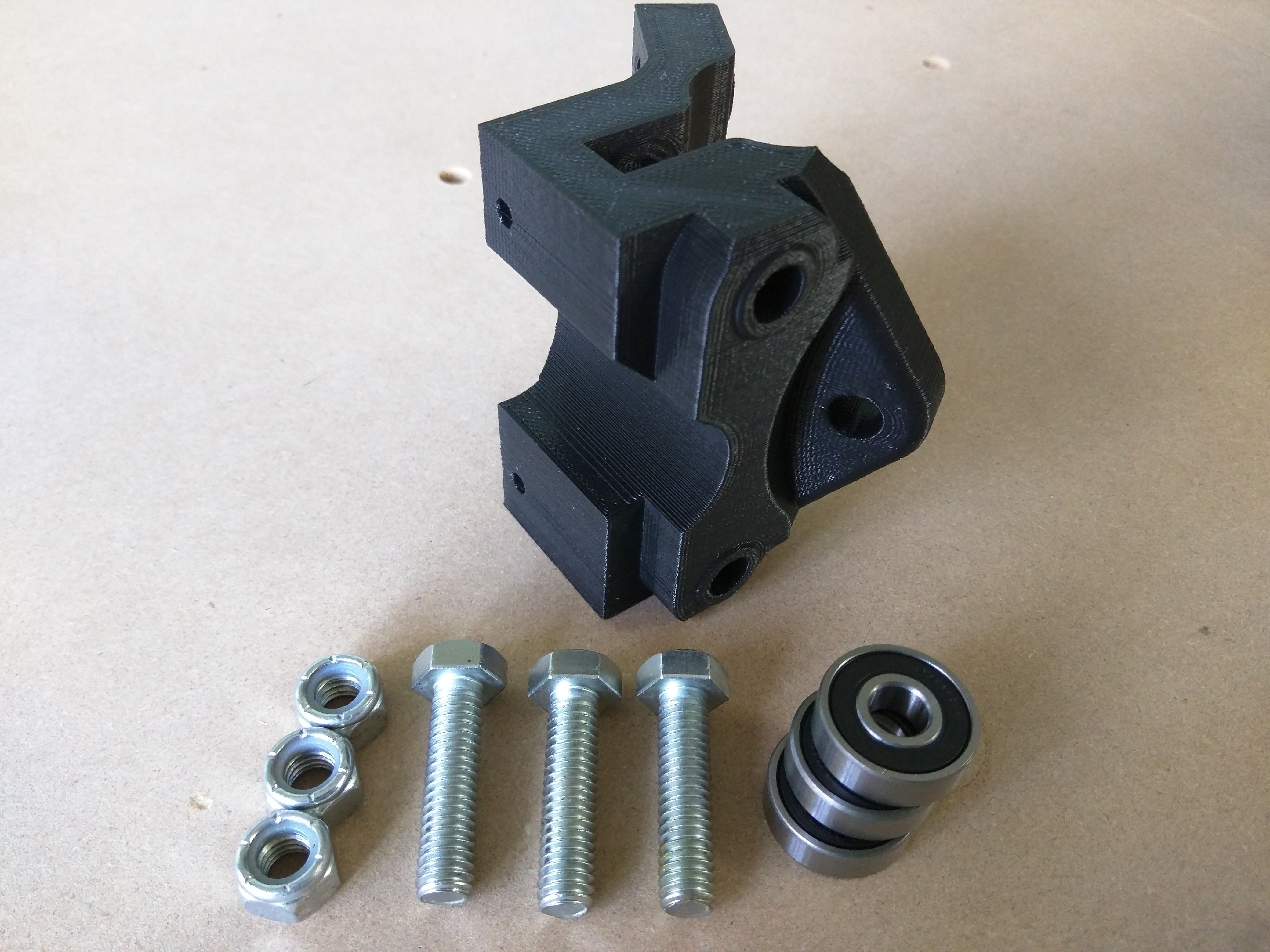
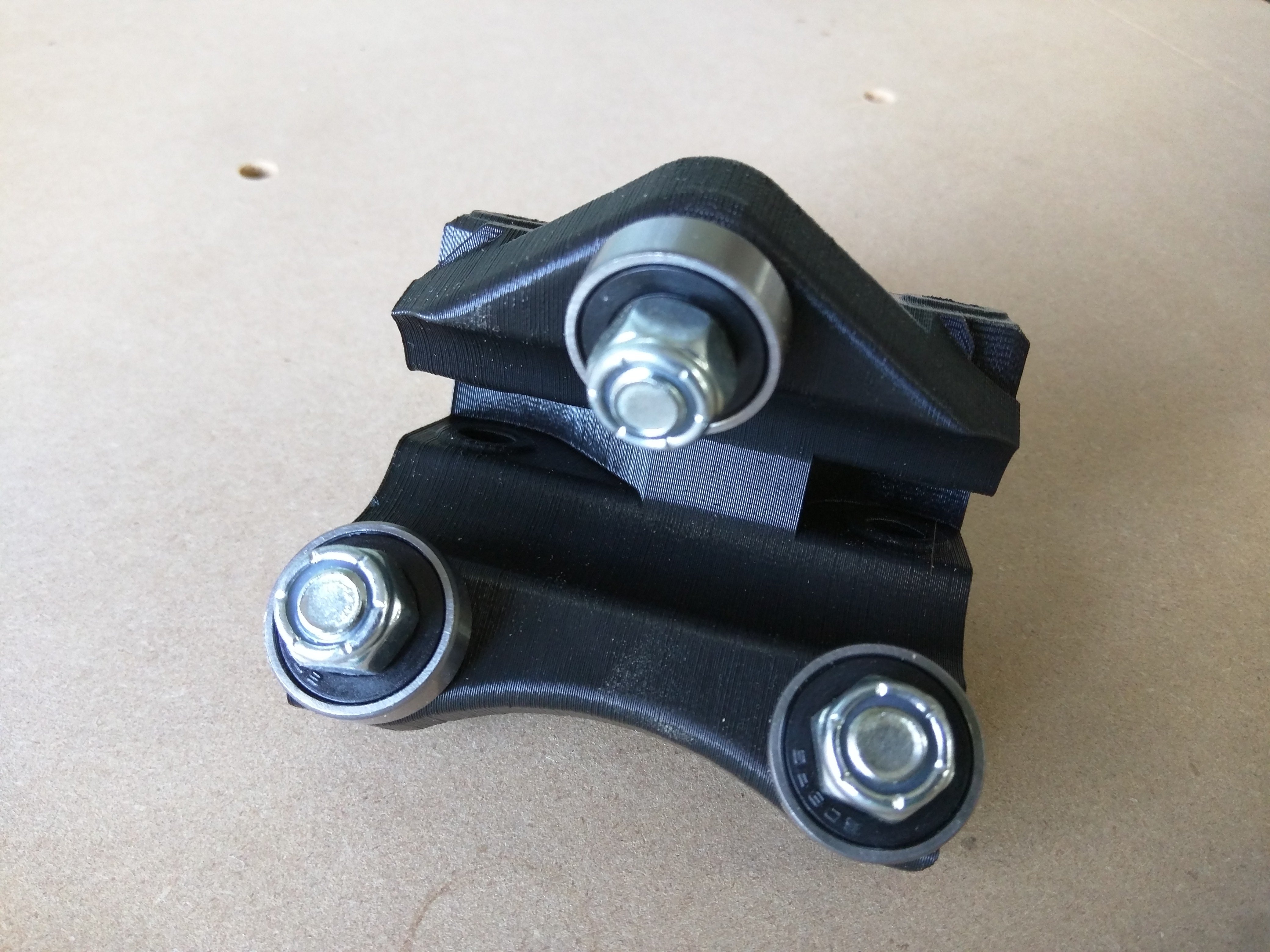
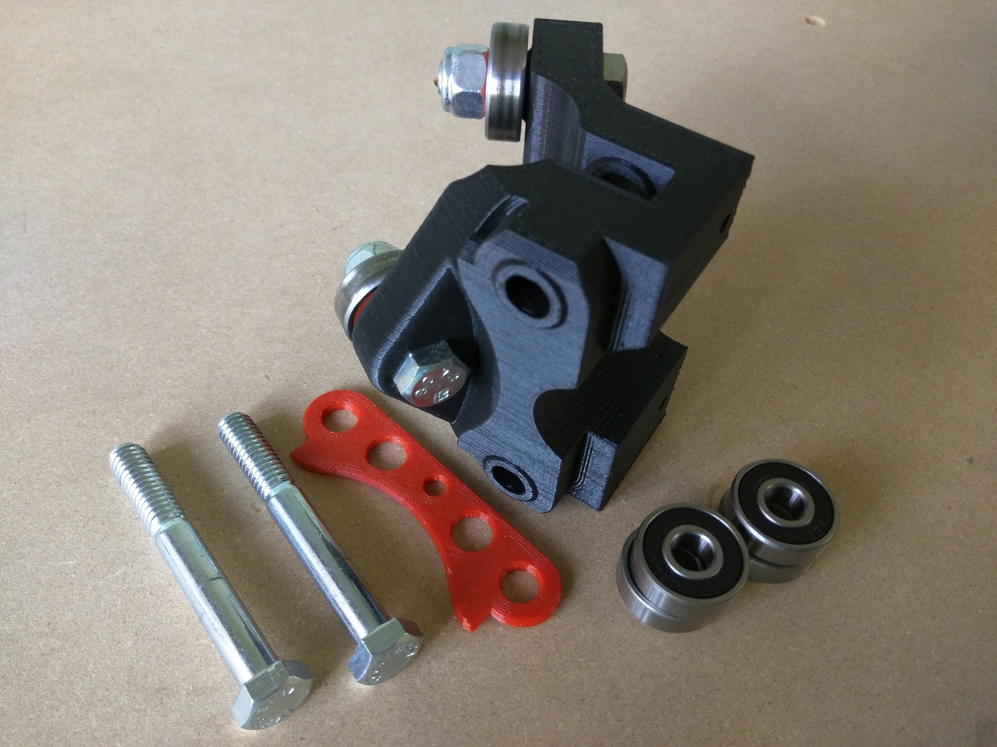
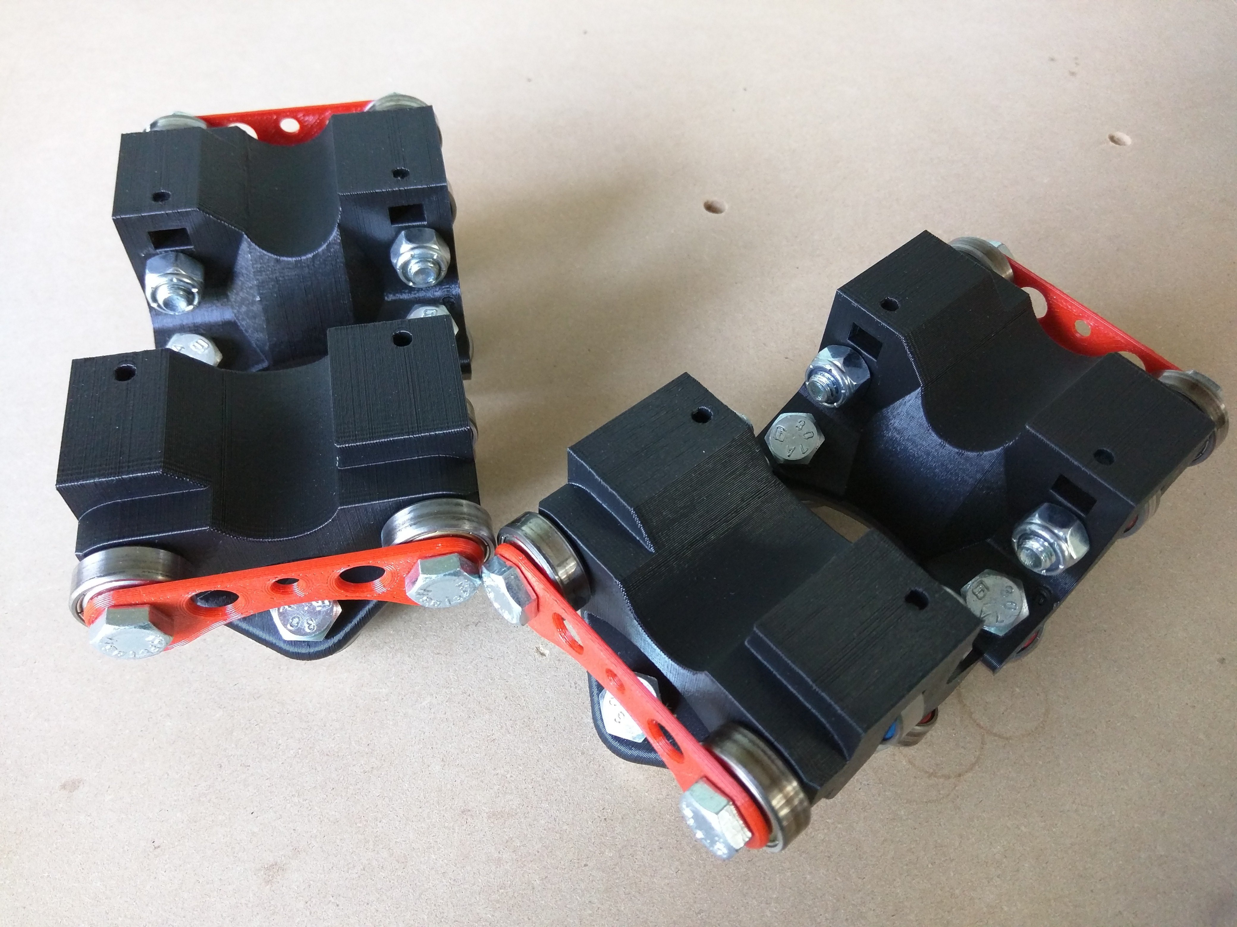
- Use the 1.25″ (M8 X 30) bolts, lock nuts, 608 bearings, and the Roller or RollerM.
- Nuts are best facing towards each other, unless you plan on adding mid span supports then the other way could get you some extra clearance.
- These can get snugged up, don’t crack the plastic, just snug.
- Do this for all 4 sets.
Roller Assembly - Tension Bolts
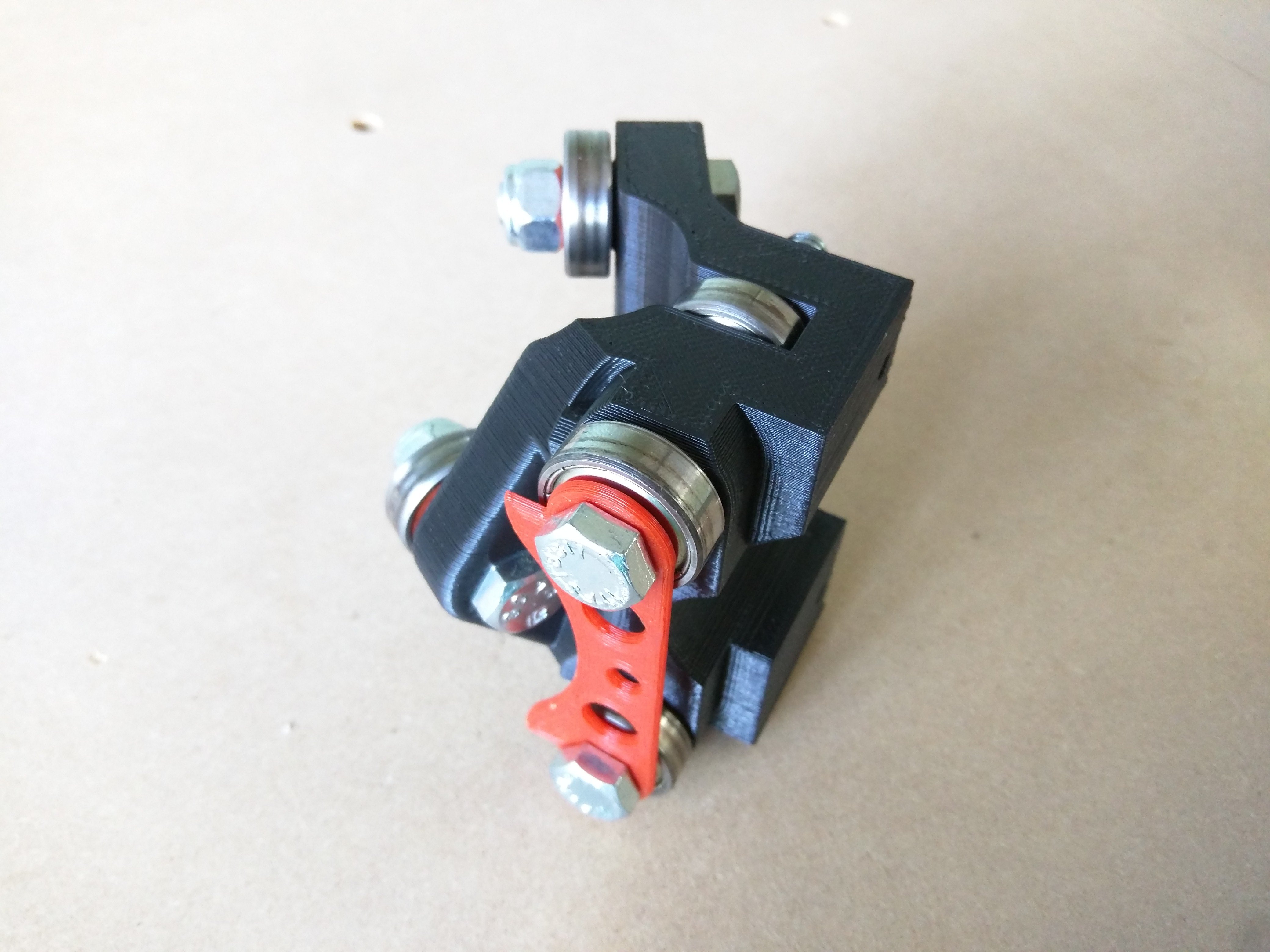
- 2.5″ (M8 X 65) bolt, 608 Bearings, Roller or Dual plates.
- Use the 2.5″ (M8 X 65) bolt, run it through the Roller Plate (or the dual plates).
- After the Roller plate add a 608 bearing.
- Add the plate and bearing stack into the Roller from the single bearing side. Only part way
- Add a Bearing into the center of the roller, and thread the bolt the rest of the way into the roller.
- Pay attention to the direction of the plate, the stand offs should face the bearings, and the extra notches should face the single bearing.
Rollers on Rails
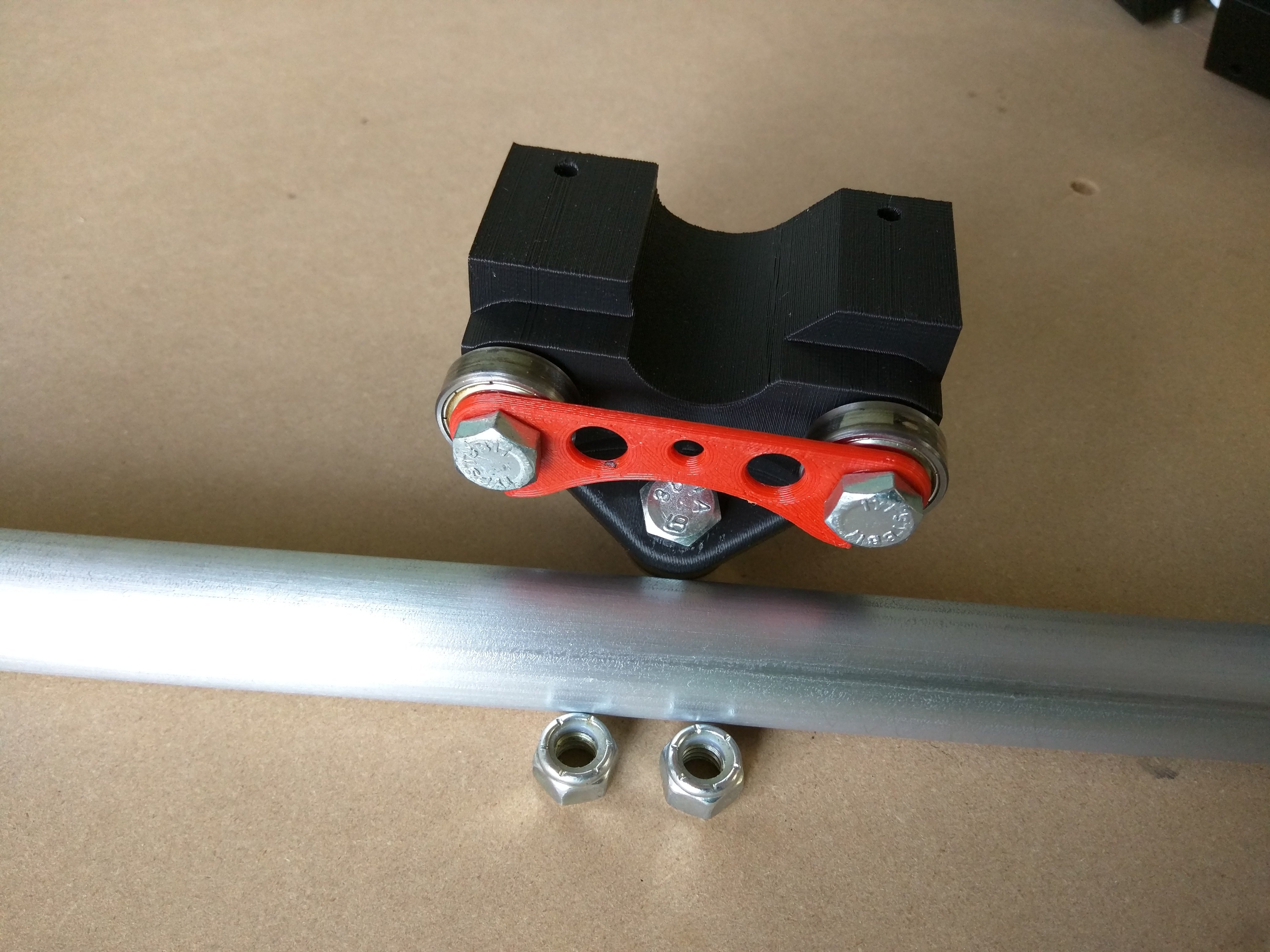
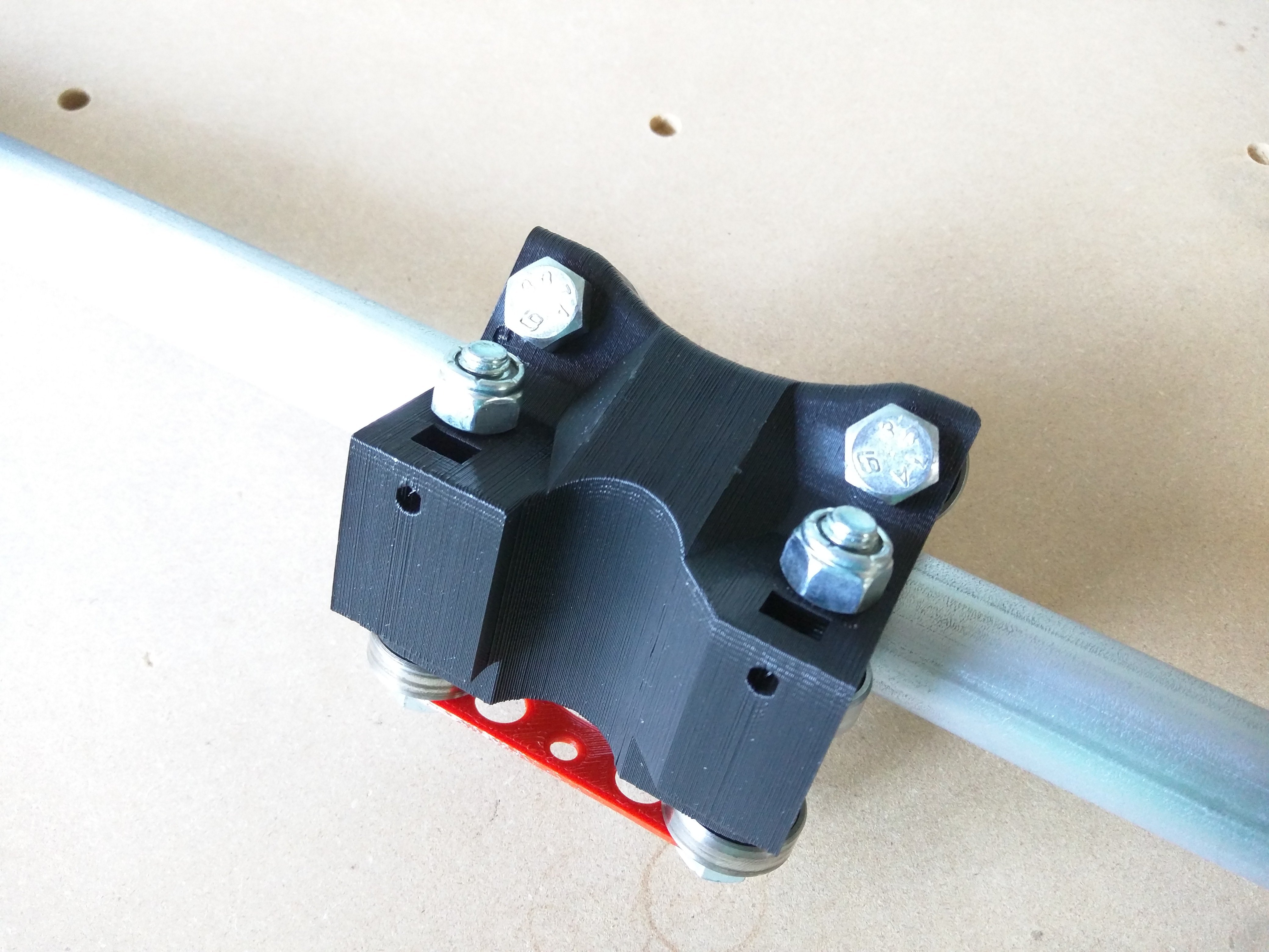
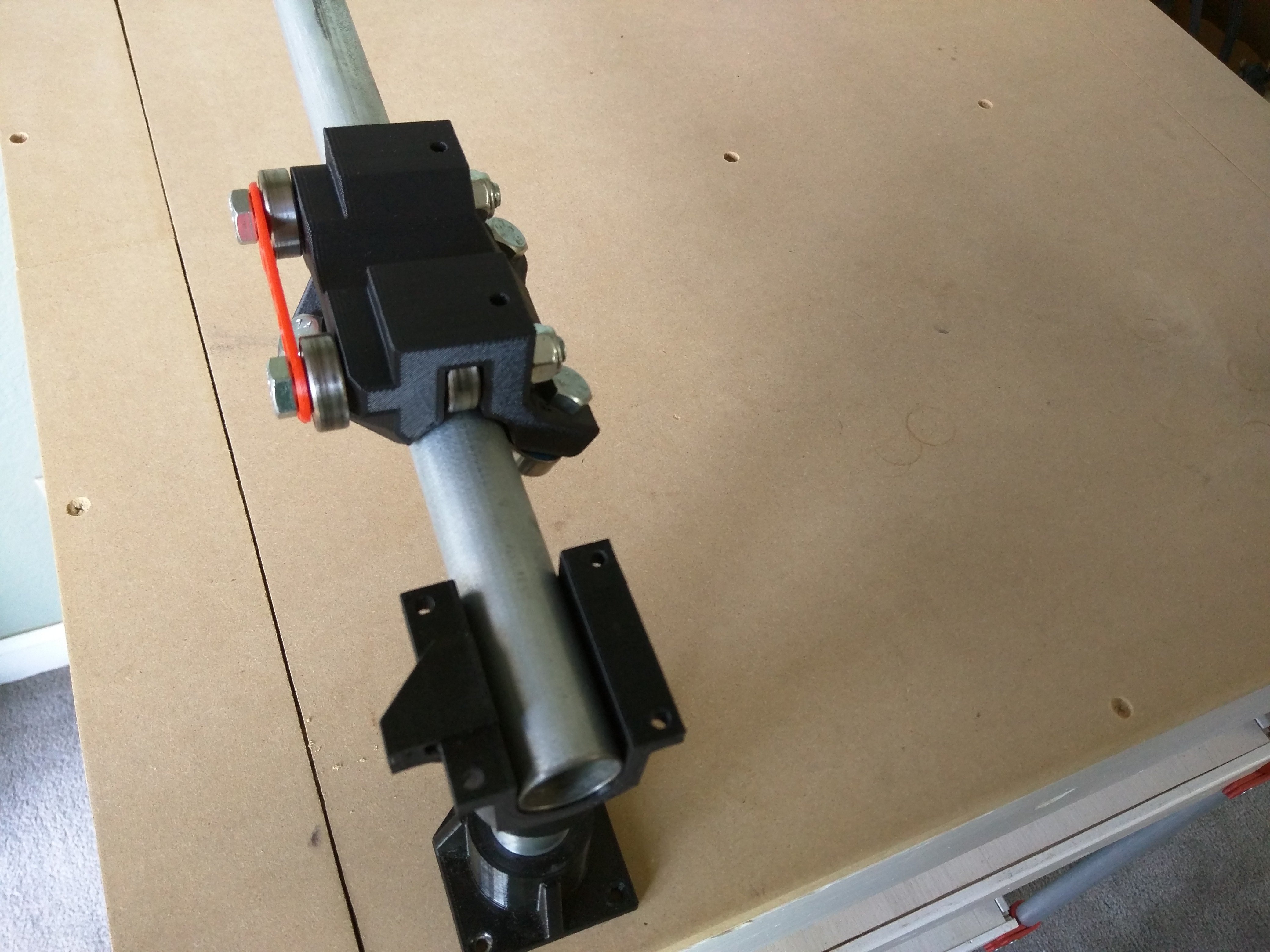
- Previous assemblies, 5/16” (M8) Nylock nuts, X or Y rail.
- The nut for the 2.5″ (M8 X 65) bolt should be left extremely loose almost touching the roller but not all the way.
- Make sure these nuts don’t interfere with the small nut slots, if they do put the small nuts in now.
- Put all the rollers on their rails and make sure they all slide equally well. There should be tension when inserting the rail and all the bearings should touch.
Roller Matched Pairs
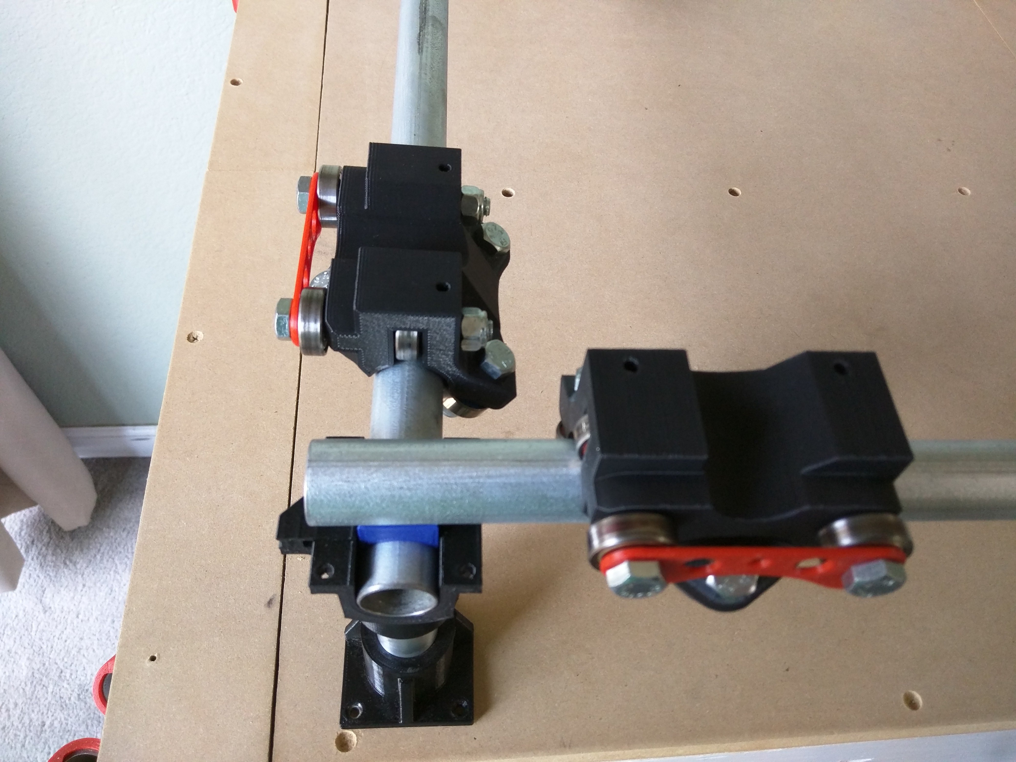
- This is showing the pairs for the X and Y axis. It should be one Roller and one RollerM. It does not matter which way the gantry rail angle is facing as long as it is facing the same as its counterpart.
- Roller and RollerM are just a mirrored set, made to help with printer deficiencies. Each axis gets one of each and the need to look mirrored (angle on the same side).
- When using the optional Dual plates, the long side should face X0 Y0 (nearest left corner)
Lower Corner Assembly
- Previous assemblies, Spacer_corners
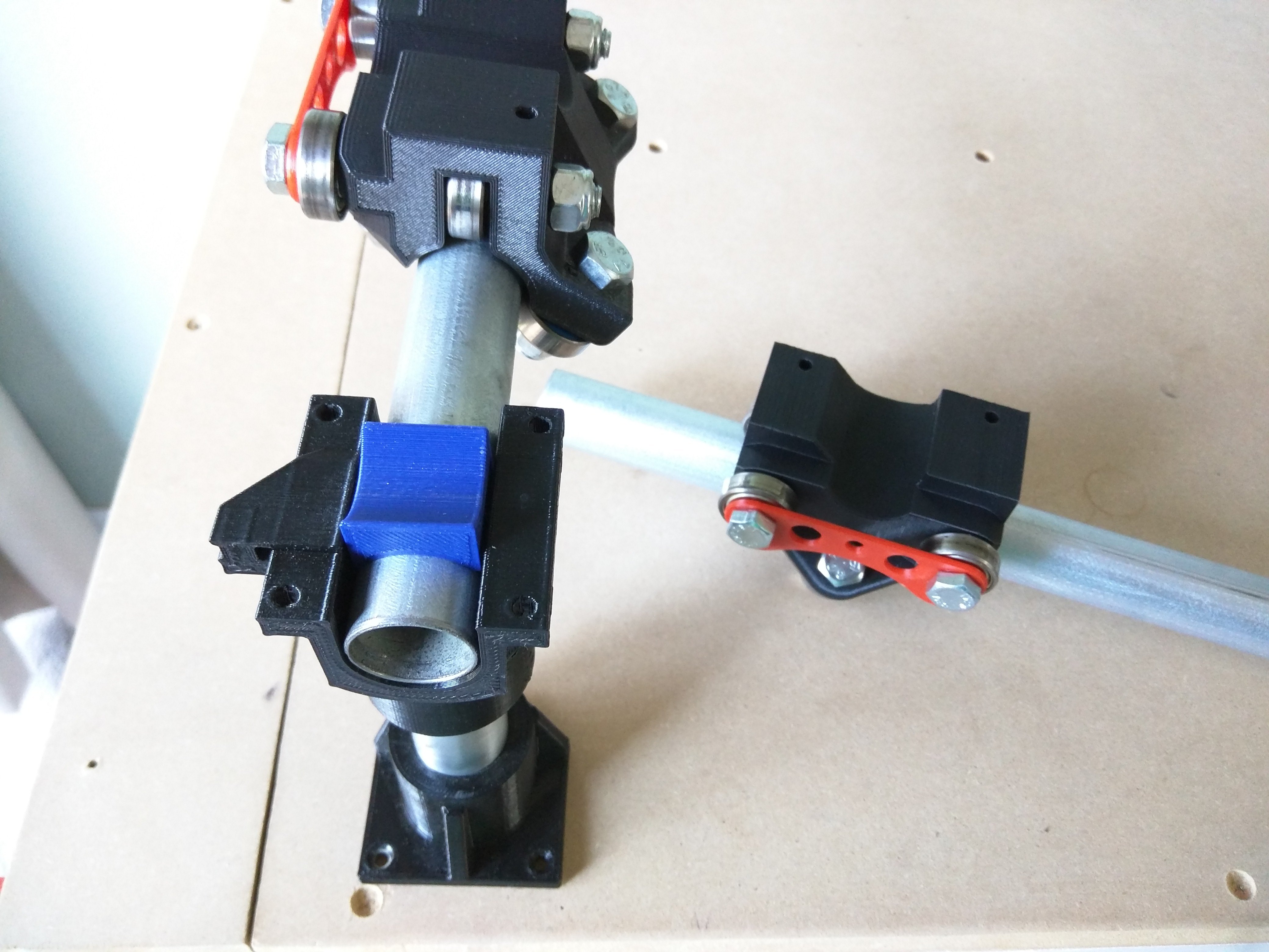
- Add your Y rails and rollers to the corner assemblies (front to back axes).
- Make sure the angled belt brackets face out, and the angles are pointed towards each other.
- Lay a Spacer_Corner on the rail.
- Lay the X rail and rollers on next (Right to left axes).
Full Corner Assembly
- Top_Corner pieces, ¾″ (M4 X 20) screws, and nuts.
- Put on the Top_Corner pieces.
- Make sure the brackets are facing out, and the angles towards each other.
- Add the four screws ¾″ (M4 X 20), and nuts.
- Leave the screws loose.
- Assemble all the corners.
- There will be a 2+mm gap all the way around.
Check Base Dimensions
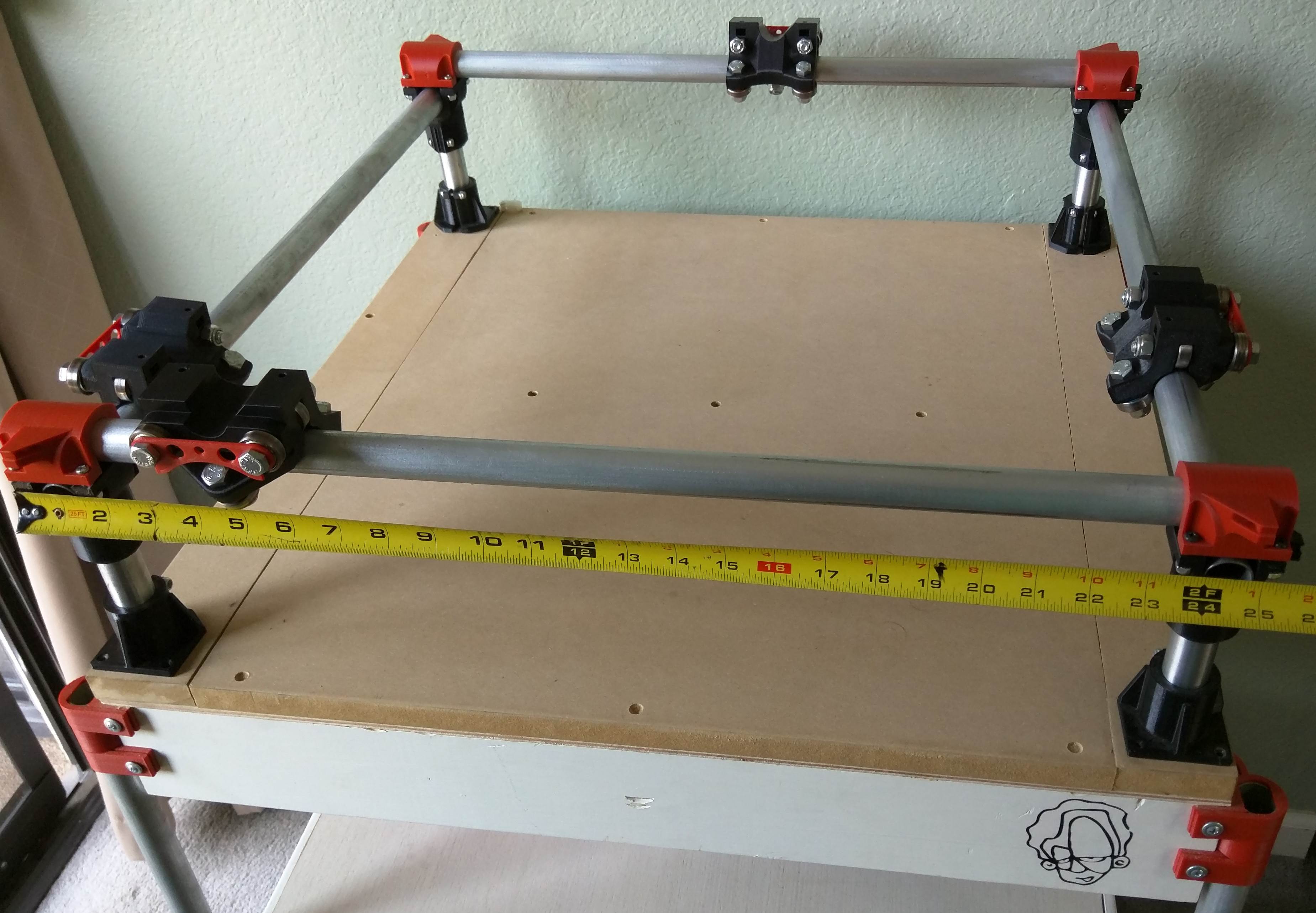
- Set all your outer dimensions from corner to corner, Usually this is the same as your x and Y Rail length that was entered into the calculator.
- Lightly snug up the Top_Corner screws trying to keep the spacing even on all four sides of the part. The parts do not require very much torque the design holds the rails well.
- There will be a 2mm+ gap all the way around.
- Double check your dimensions, Be as accurate as possible.
