MP3DP v5 CoreXY
This is the 3rd CoreXY version for me, 5th printer design overall. This printer was a group effort and a direct result of everyone’s input, Forum Thread
This is a CoreXY with easily machinable plates for ultimate rigidity where it counts but 3D printed parts where it does not matter to save from complicated multi-sided milling.
Belted Z axis, with free floating bed to allow for physical tilt correction as well as mesh correction, and possible non-planer printer in the future. Electronic brakes provide easy drop protection for the bed.
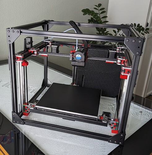
This first build of mine has a 300x300x200 build area, running Klipper, Costs about $800. Forum Thread.**
Warning
Note for potential builders
If you are thinking about building a printer… a V1 Engineering CNC is an easy to intermediate build, a 3D printer is an advanced to expert build. A lot of personal build decisions need to be made, wiring is on the advanced end, firmware edits are required, CAD reference and possible edits are required, and overall build precision is higher.
Because the builds vary, so wildly, instructions might not exist for the exact combination of hardware and electronics you choose. As always you can come here for help but if you chose random parts we might not have enough experience with them to help. If you are on the fence and want to tackle this, it would be best to follow my build exactly.
Parametric Options
If you want a printer that is different than the standard build size, or has a custom extruder/hot end, you’ll need to edit some parameters in the CAD file to generate the correct part sizes for your build.
CAD link - Fusion, Fusion360 archive file.
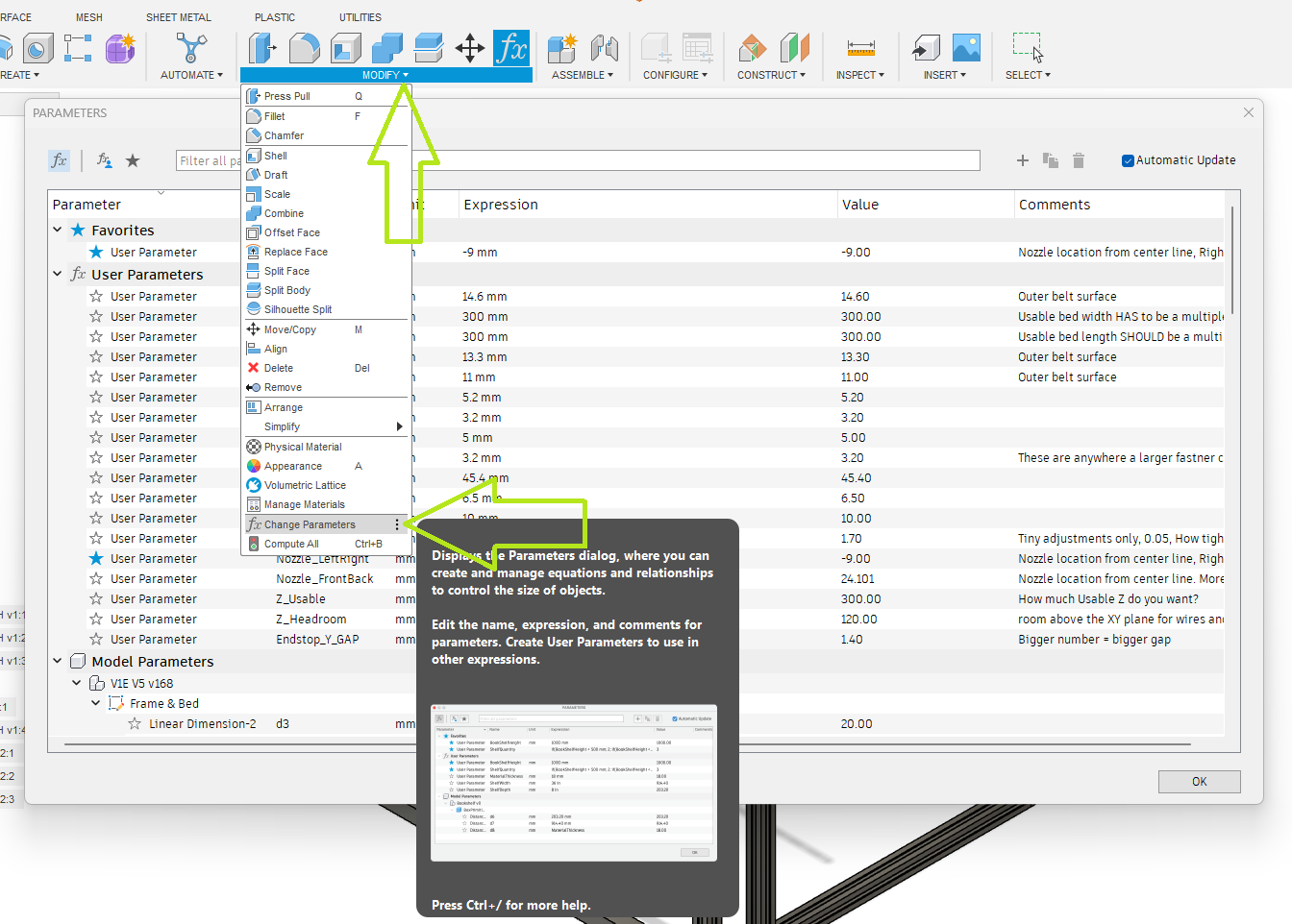
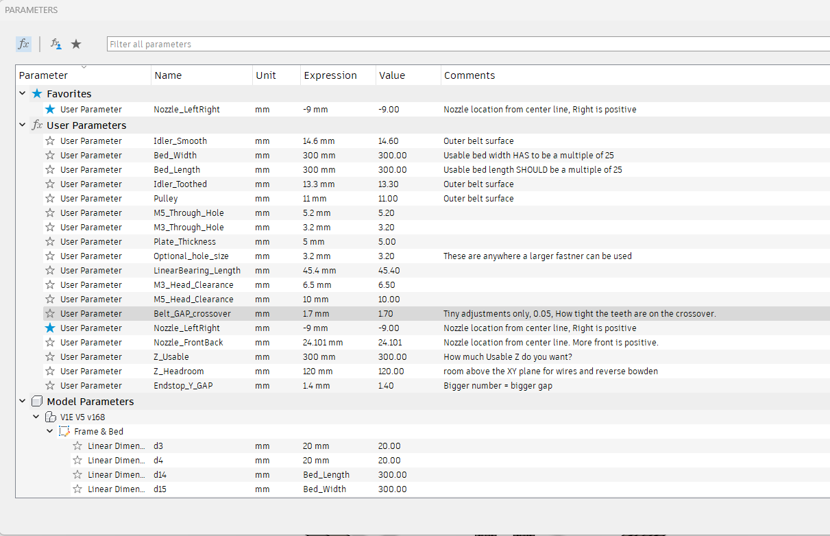
This is how you adjust the model. Open the modify menu, Change parameters Menu.
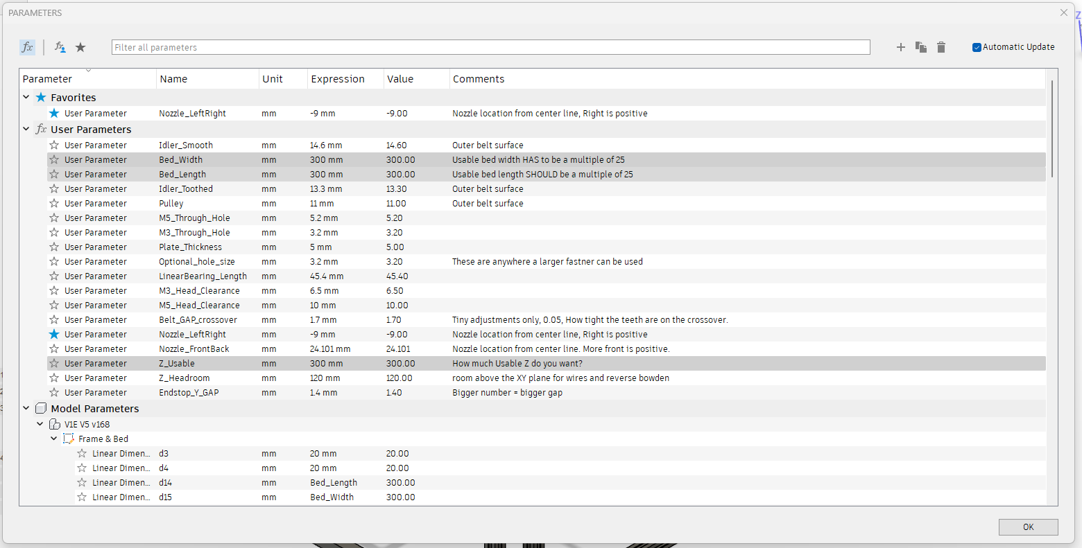
Build Size
Note
The Three Bed cut parts (Bed A-C) are the only parts that are size dependent. Make sure to set the correct build size before cutting these parts. 300X x 300Y is the default included size.
These three settings are how you adjust the size of the build. Z is not exact as it depends on the hotend you chose but it should be close.
Note: The CAD will fail if you go up and down in size. Make one edit and it should be fine. If you have an issue, start fresh.
Optional hole size
This lets you adjust the hole size for the Plates to frame.
I was asked to allow for M5 hardware. This is where you do that. You will need to export new DXF files for the corners and tensioner parts.
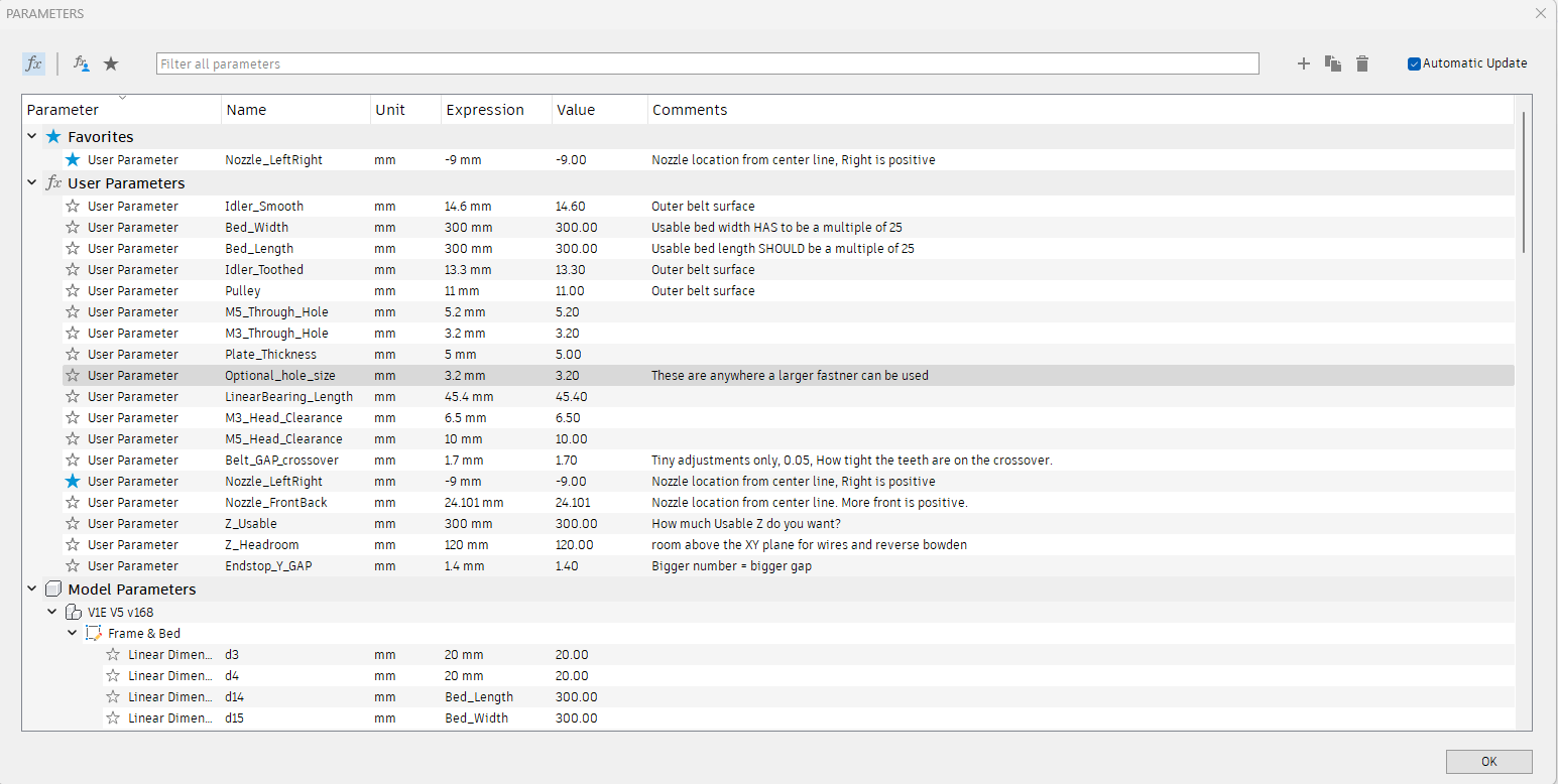
Belt Grip
If you want to make the Belt have a tighter or looser grip on the core bottom or Z top pieces, you can change it here.
CAD Help
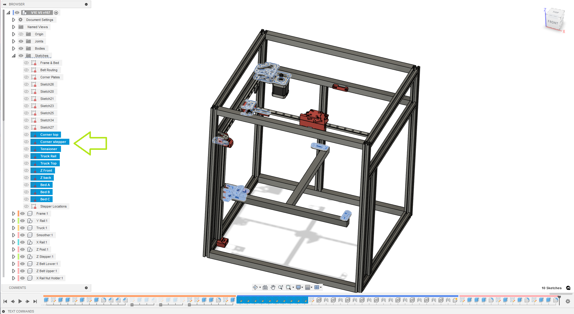
Exporting DXFs
If you want to export your own DXF’s this is where you find them.
 or you can use this svg
SVG Panel
or you can use this svg
SVG Panel
BOM
Flat Parts
The flat parts are designed for you to be able to mill them yourself with your MPCNC or LowRider out of 3/16” (4.7mm-5mm) aluminum.
Note
The Three Bed cut parts (Bed A-C) are the only parts that are size dependent. Make sure to set the correct build size before cutting these parts. 300X x 300Y is the default included size.
| QTY | File Name | Comment | Link |
|---|---|---|---|
| 2 | Corner Top | ||
| 2 | Corner Stepper | ||
| 2 | Truck Rail | ||
| 2 | Truck Top | ||
| 3 | Z Front | ||
| 3 | Z Back | ||
| 4 | Tensioner | ||
| 1 | Bed A | ||
| 1 | Bed B | ||
| 1 | Bed C |
Printed Parts
Printed Parts can be found here: Printables
No supports needed, keep the default orientation. PLA is recommended for ultimate rigidity, other filaments should be evaluated for rigidity. 2-3 walls rectilinear infill.
| QTY | File Name | Infill | Comment |
|---|---|---|---|
| 1 | Core Top* | 55% | |
| 1 | Core Bottom* | 55% | |
| 3 | Z Belt Lower | 40% | |
| 3 | Z Belt Upper | 40% | |
| 3 | Z Stepper - Z Bearing Mount | 40% | |
| 6 | Z Stepper - Z spacer | 40% | |
| 3 | Z Stepper - Bed Mount | 40% | |
| 2 | Y Truck | 40% | |
| 4 | Y Truck - spacer | 40% | |
| 2 | X Rail - Nut holder | 40% | |
| 4 | Rear Spacer | 40% | |
| 1 | Smoother | 40% | |
| 2 | Front Spacer | 40% |
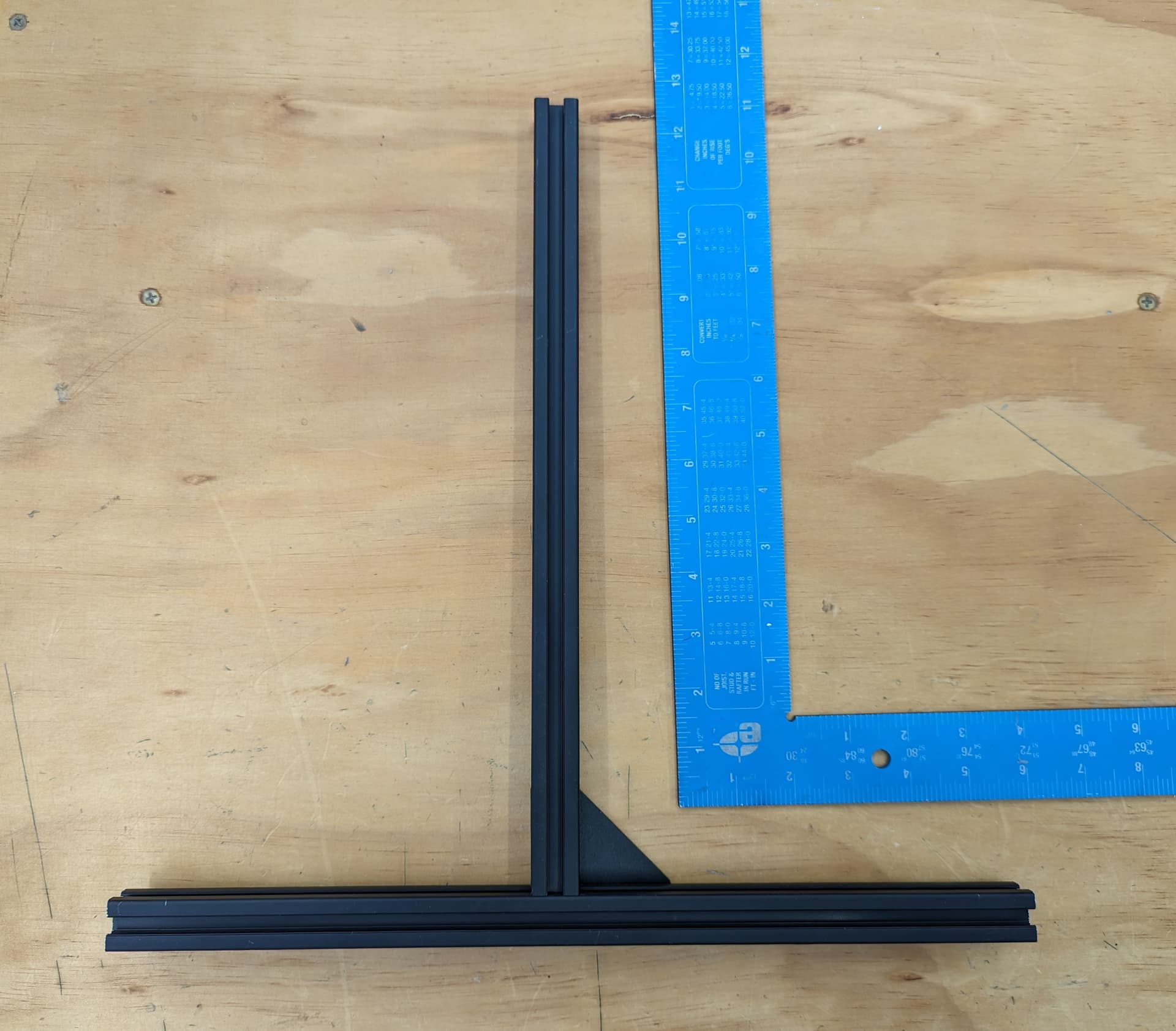
Frame
The frame is built with 2020 extrusion.
Cuts should be planned carefully to reduce waste. A site like Opticutter can be used to verify the amount necessary for your printer size.
It is highly recommended that you calculate this before ordering your extrusion to reduce potential extra cost
Extrusion List
There are 20 total pieces of extrusion that need to be cut
| QTY | Name |
|---|---|
| 6 | Y Rails |
| 5 | X Rails |
| 4 | Z Uprights |
| 3 | Z Linear Rail Mount |
| 1 | Bed Support 1 |
| 1 | Bed Support 2 |
*Cut all extrusions 2-3mm short. This lets you have not perfect cuts and still build an extremely accurate frame.
Bed Parts
Bed is held by the two bed supports and a spacer of some sort. It could be a couple ¼” pieces of plywood or aluminum. the heavier it is, the greater chance the bed will fall and power the electronics as it does so. Countersunk holes in the spacer will allow the bed to lay flat. A channel for the bed heater wires may be required at the top.
Extruder
Extruders are availble - V1 shop
Frame
2020 Extrusion - Amazon
Electronics
At the minimum, a control board with 6 channels is required: coreXY motors (2), self leveling Z movement motors (3), and Extruder (1). An skr pro 1.2 is adequate. A BTT octopus or manta with 6+ motor channels is also an option. If using klipper, multiple boards can be used simultaneously… one could run A and B and another for the Z channels.
Electronics part list
| QTY | Part | V1 Shop link | alternate option |
|---|---|---|---|
| 1 | 6 channel controller like skr 1.2 pro | V1 Shop | self source octopus, manta, or equivalent |
| 3 | endstop switches | V1 Shop | Amazon Affiliate |
| 1 | bl touch or CR touch | V1 Shop | |
| 1 | smart filament sensor (optional) | V1 Shop | |
| 1 | brake board for bed drop back-EMF prevention (optional) | V1 Shop | or use 3 relays |
| **** | *if running klipper************* | ****** | ******* |
| 1 | ADXL345 accelerometer for input shaping (optional) | self | source |
| 1 | raspberry pi pico for ADXL345 chip with USB to rpi below (optional) | self | source |
| 1 | raspberry pi or pc to host the klipper operating program | self | source |
Firmware: Marlin or Klipper are options. See forum for firmware inquiries or help.
Hardware
Hardware Part list
These parts are needed to assemble the belt train and motion components once the frame is built
| QTY | Part | V1 Shop link | alternate option |
|---|---|---|---|
| 8 | 20 tooth idlers, 5 mm bore | V1 Shop | Amazon Affiliate |
| 10 | smooth idlers, 5 mm bore | V1 Shop | Amazon Affiliate |
| 5 | 16 tooth pulleys with 5 mm bore | V1 Shop | Amazon Affiliate |
| 1 | X linear rail and MGN12H trolley (bed width + 25 mm) | self | sourced |
| 2 | Y linear rails and MGN12H trolly (y length + 50 mm) | self | sourced |
| 3 | Z linear rails and MGN12H trolley (height + 50 mm) | self | sourced |
| 5 | NEMA 17 motors | V1 Shop | Amazon Affiliate |
| 3 | meters of g2 10 mm belt (minimum) | V1 Shop | Amazon Affiliate |
| 1 | kit of printed parts (listed above) | user printed | prinatables |
| 1 | kit of milled parts* | V1 Shop | Self Milled (svg or dxf export listed above) |
| 31 | M5x35 bolts | self | sourced |
| 31 | M5 Nylock nuts | self | sourced |
| 3 | bed springs z movement to bed T-mount | self | sourced |
| 3 | washers for the bed springs | self | sourced |
| ~90** | M3x10 screws for rails, milled parts and mgn12h | self | sourced |
milled parts can be milled from 5 mm - 6.35 mm (¼“) thick aluminum or even laser cut from 5 mm - 6.35 mm thick acrylic if desired. *M3 bolt count does not include extrusion structure and enclosure bolts. These are for holding the motors and the motor mounts and printed and milled pieces as well as the linear rails and trolleys together.
Assembly
Frame
The process is very similar for a corner bracket frame. Panels are easier to build but harder to make.
Building on a very flat and solid surface will make this part easier.
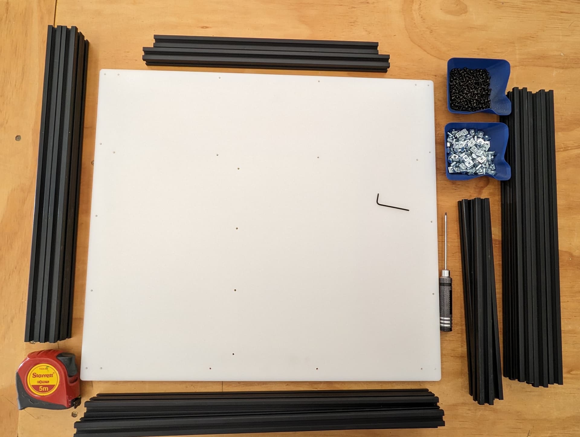
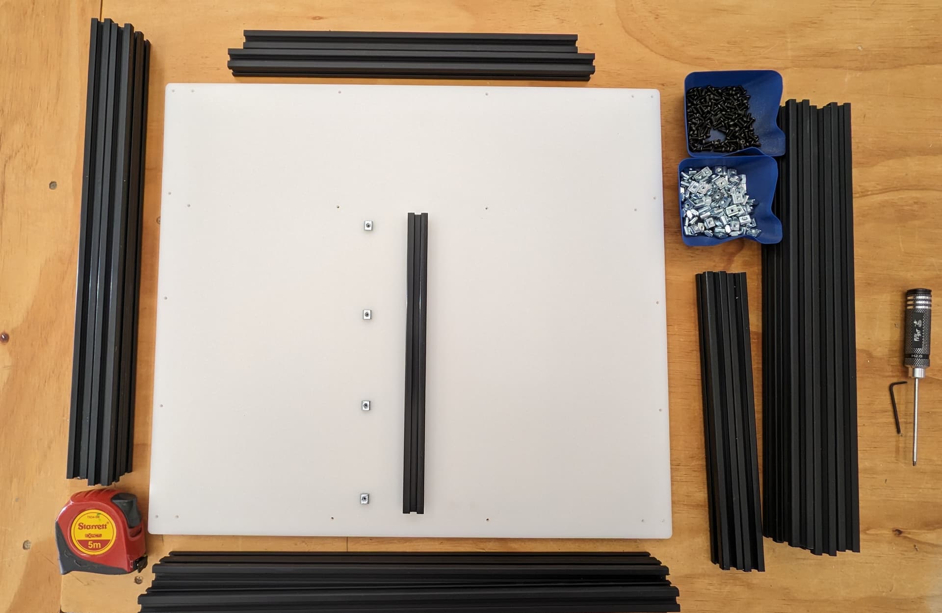
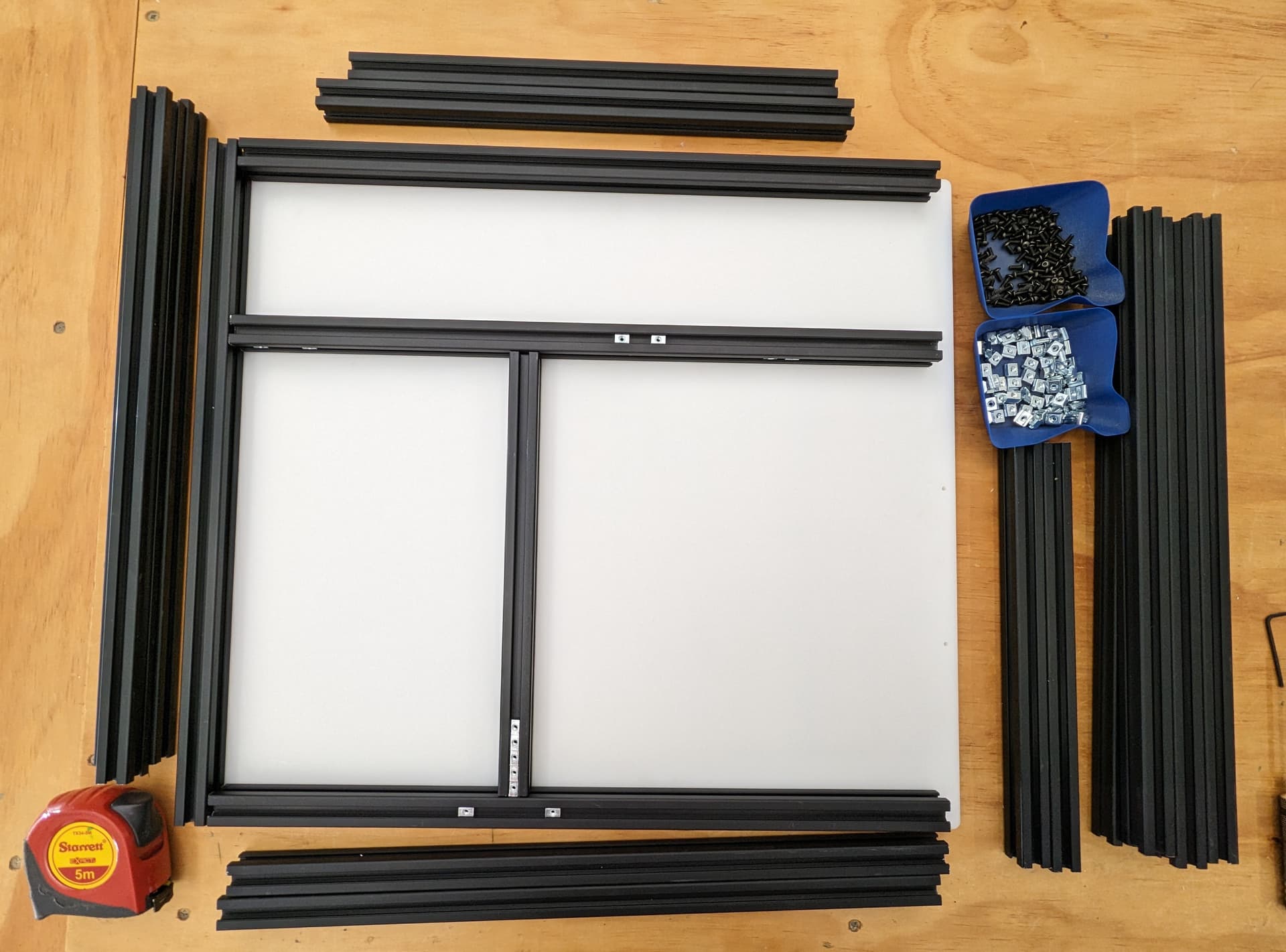
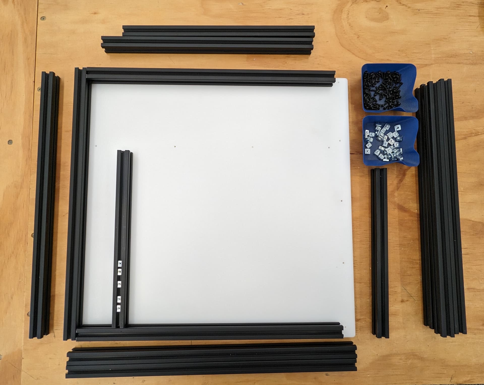
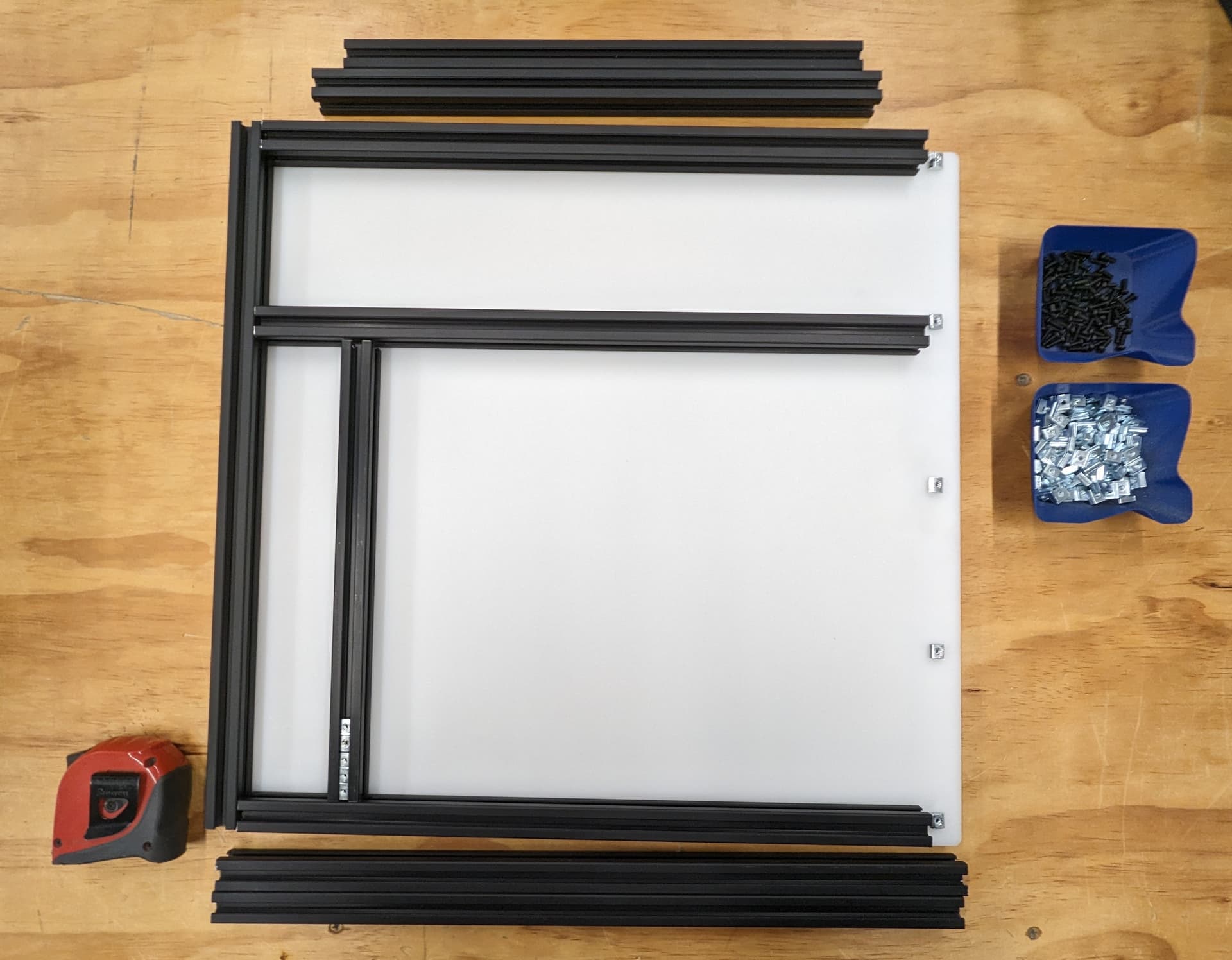
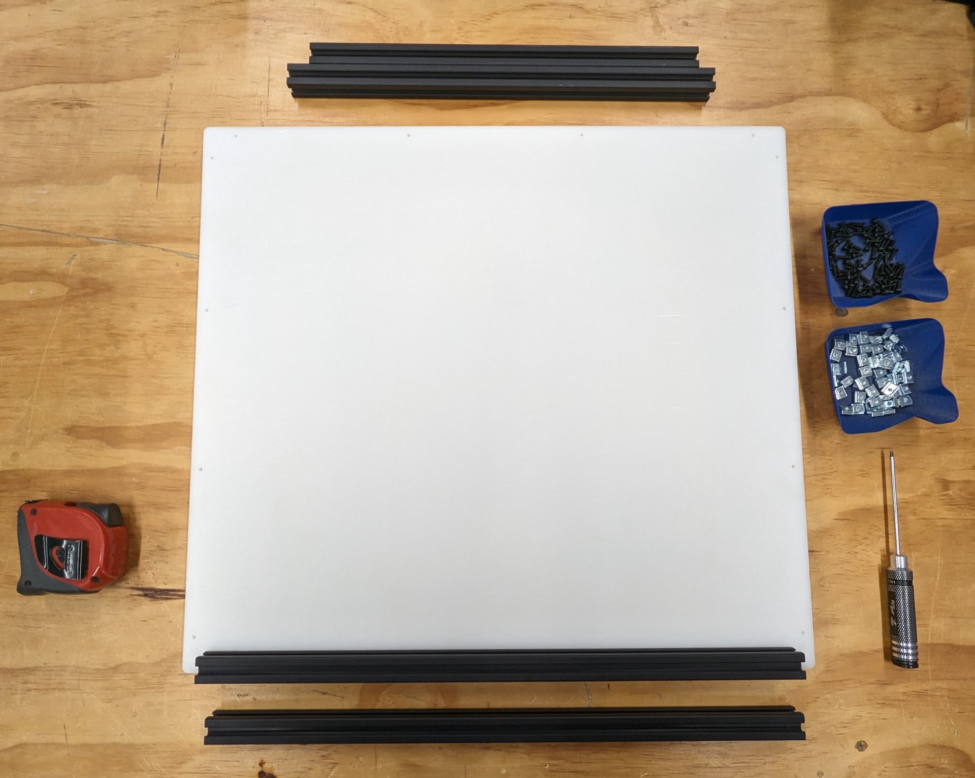
Frame parts and tools. We will start with the back panel.
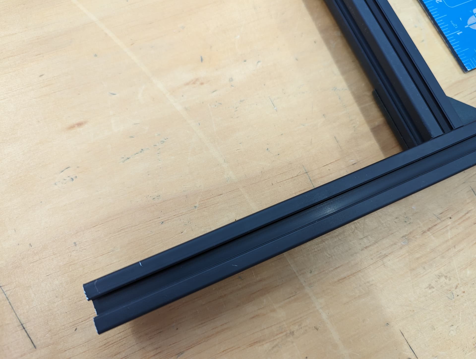
Load up the t-nuts. It’s important at this stage to insert all t-nuts that will be necessary if you are using the trapped t-nuts instead of twist-ins. I only use twist in’s when I forget to load one in.
Slide the extrusion on. Going to use this same process a lot.
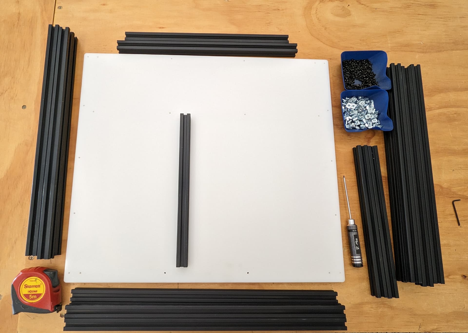
Top and bottom
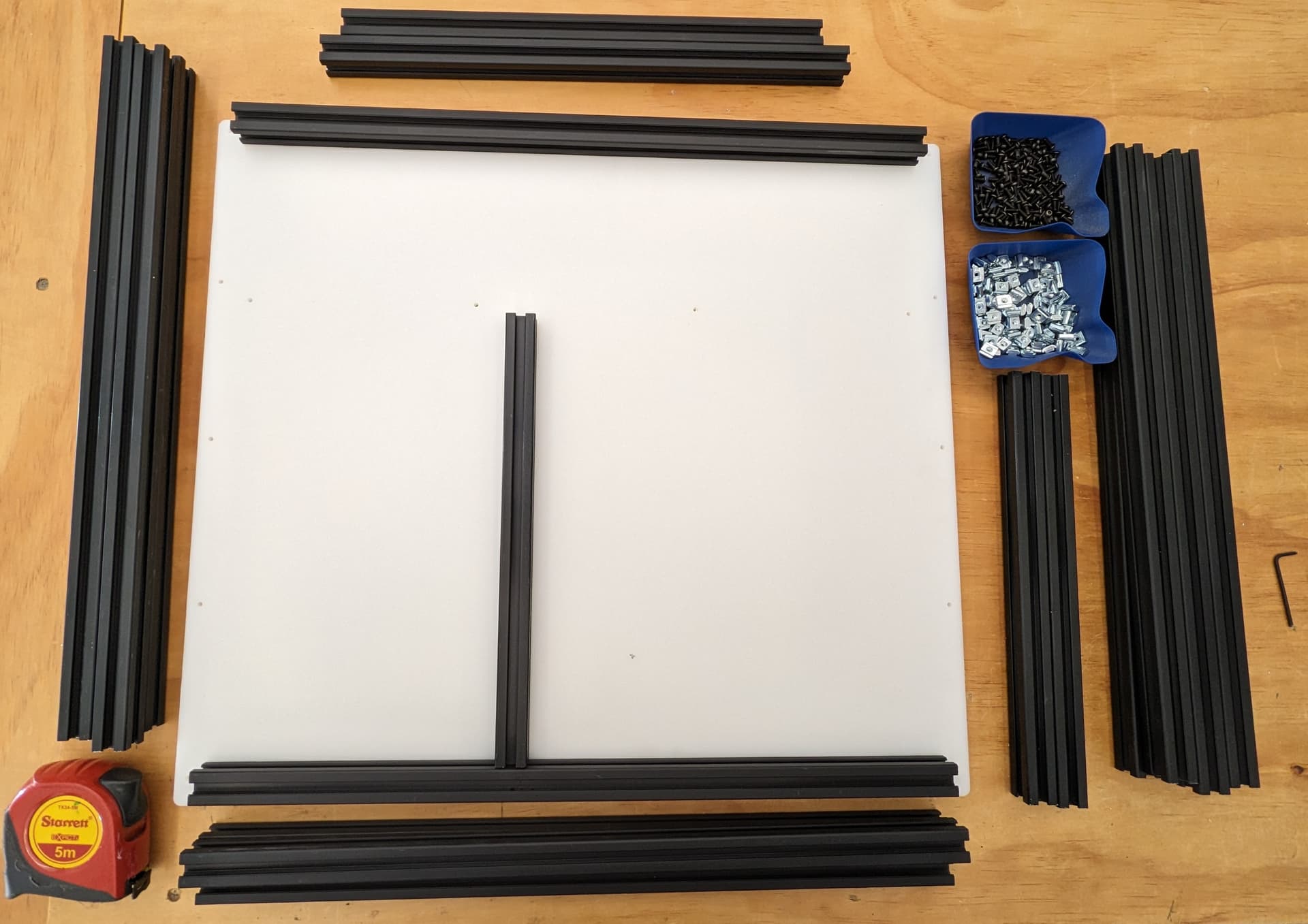
Load in the trapped Tnuts (if you are not using twist in’s).
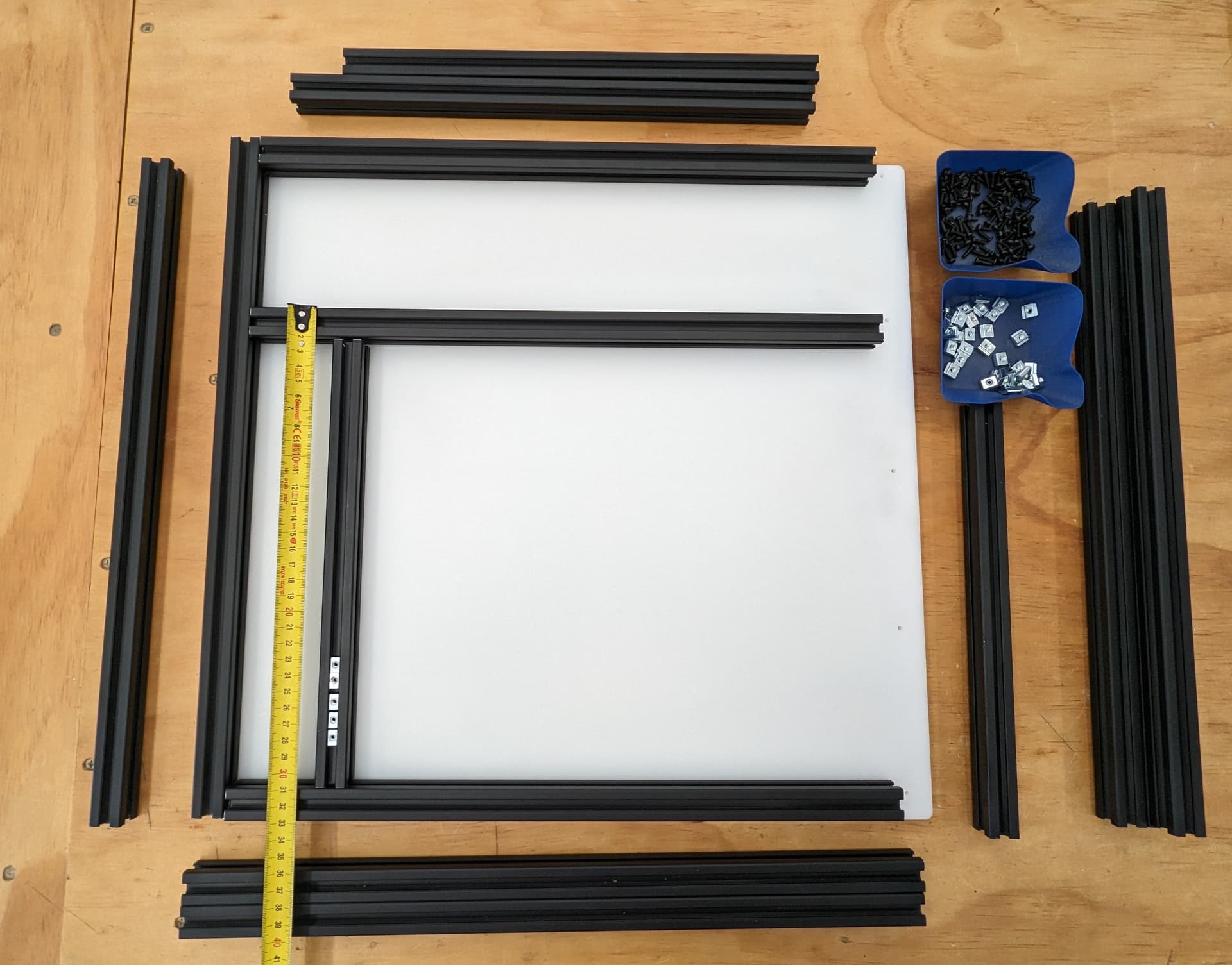
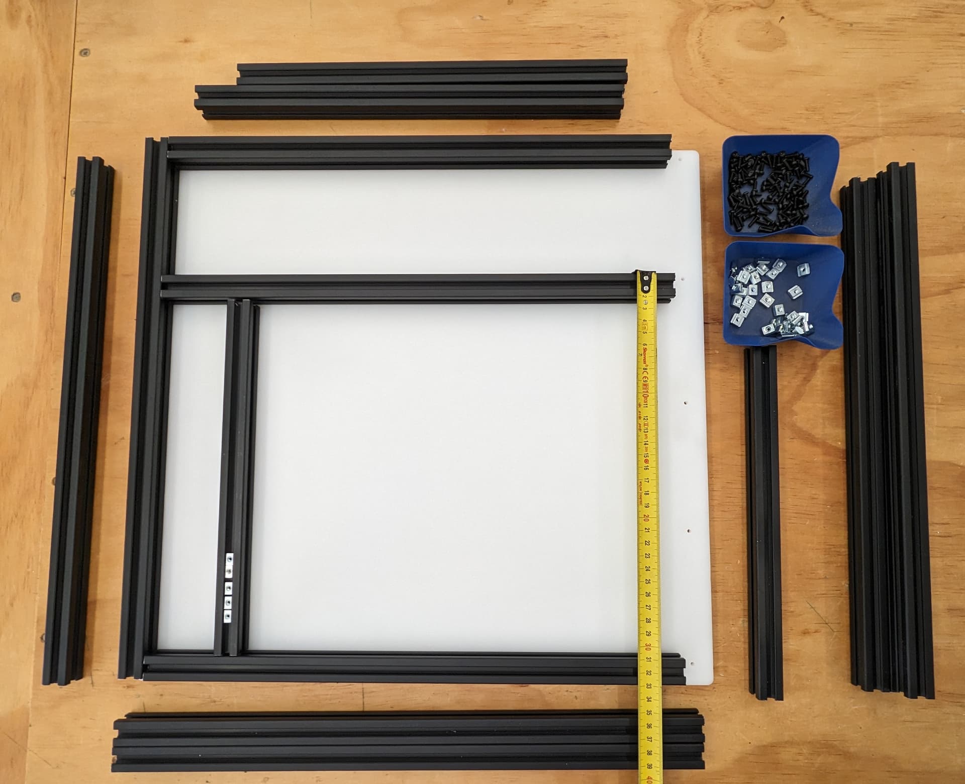
Add the other rails, load in more trapped T nuts. Remember top and bottoms as well.
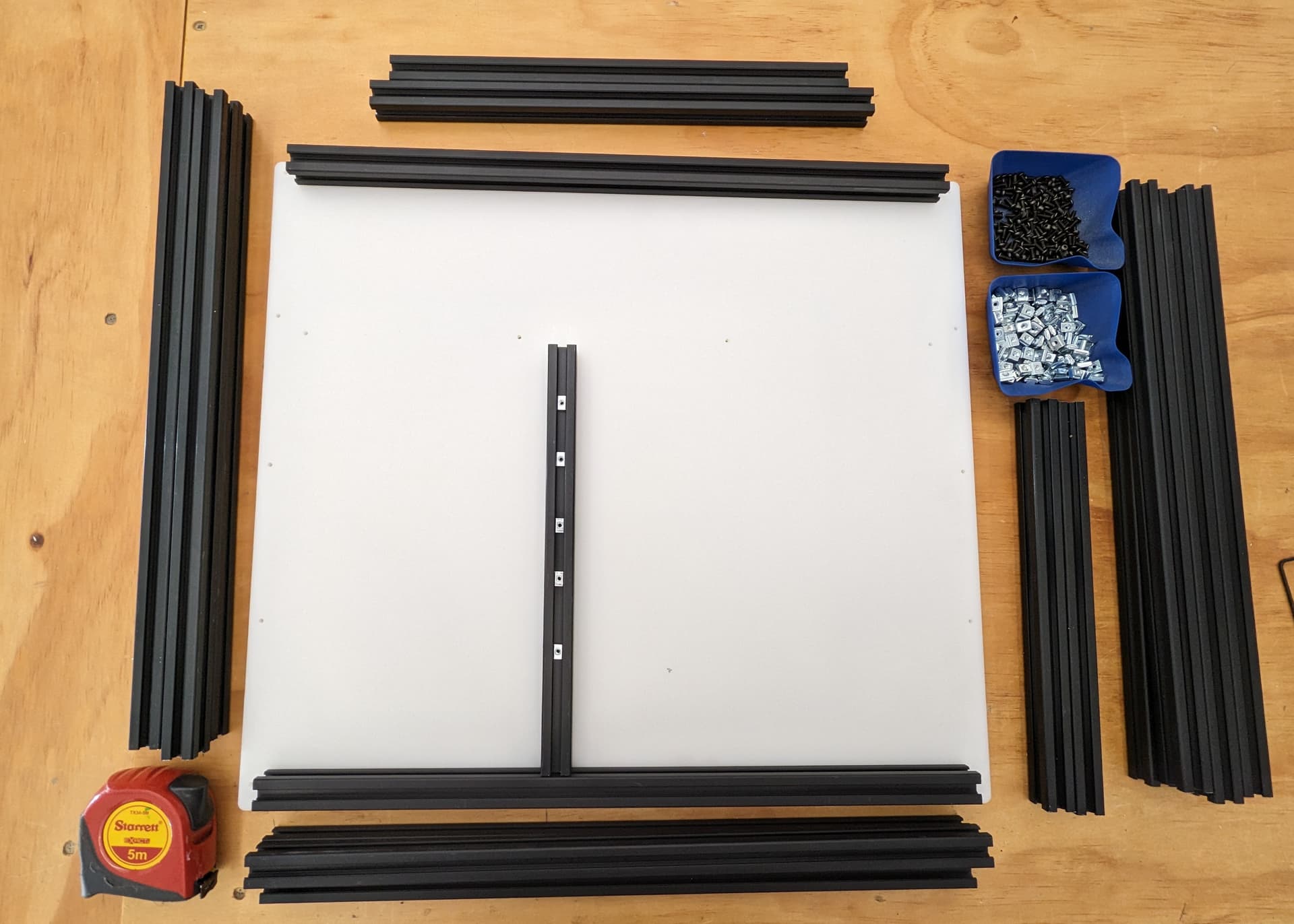
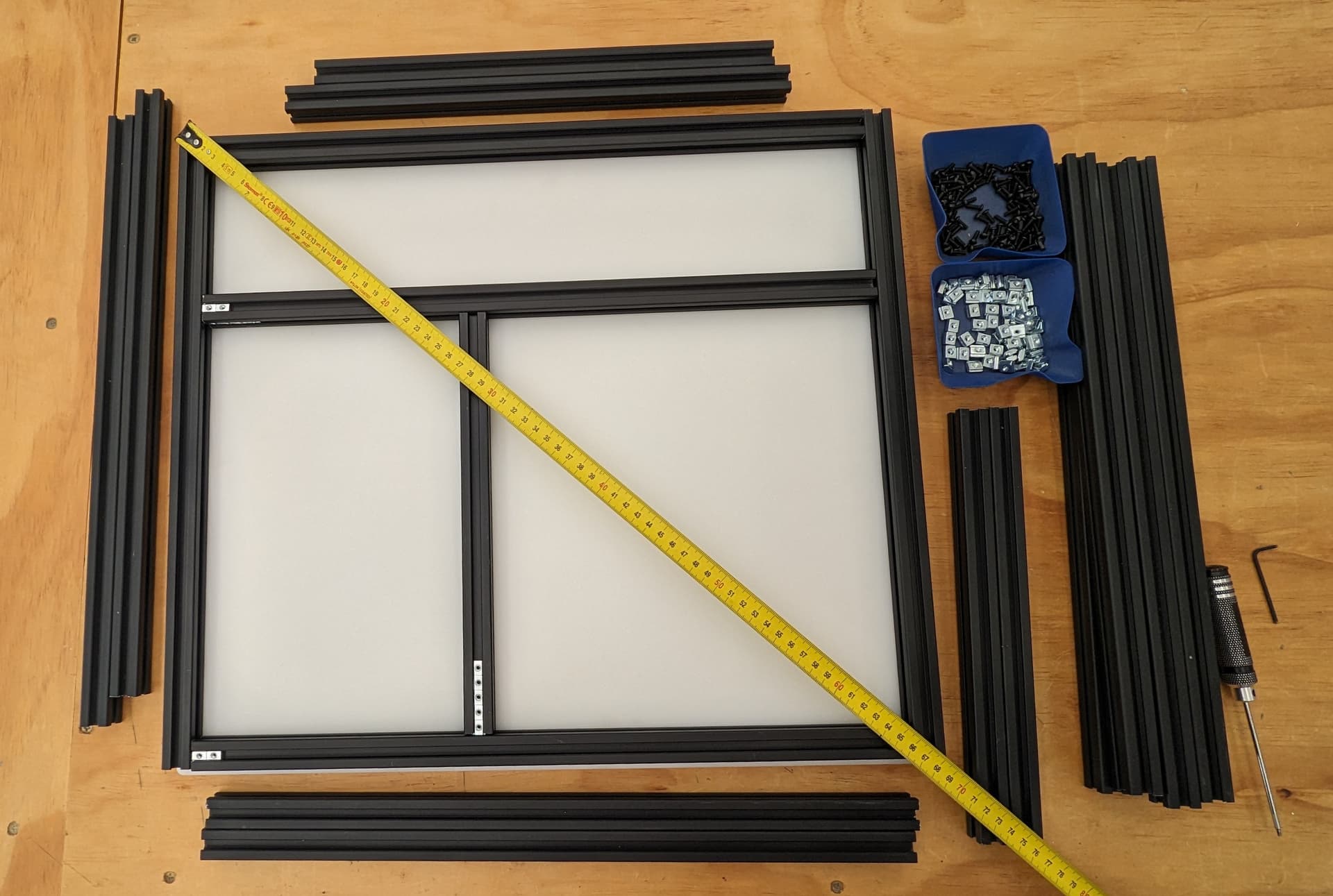
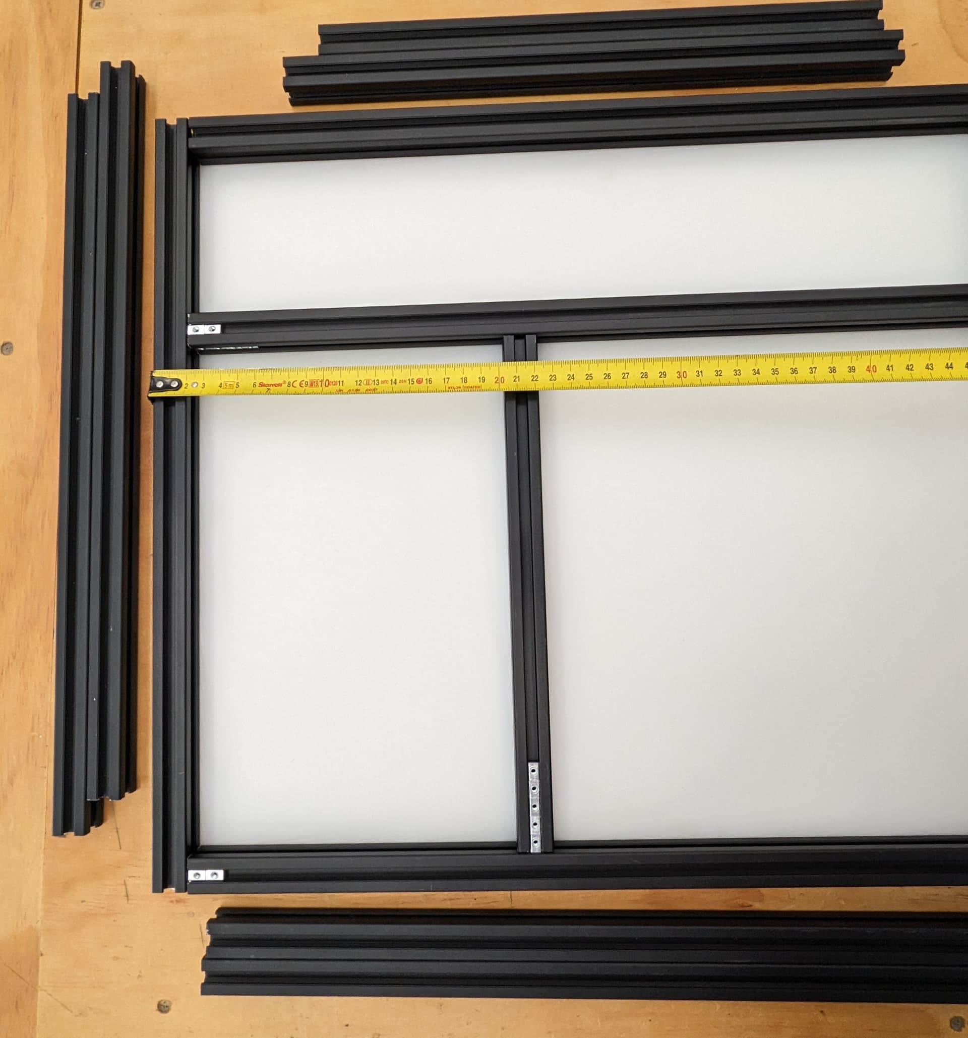
Add last rear rail. Verify all dimensions, Diagonals are very important as well (cut ends are not accurate to measure from so inside corner to inside corner works best).
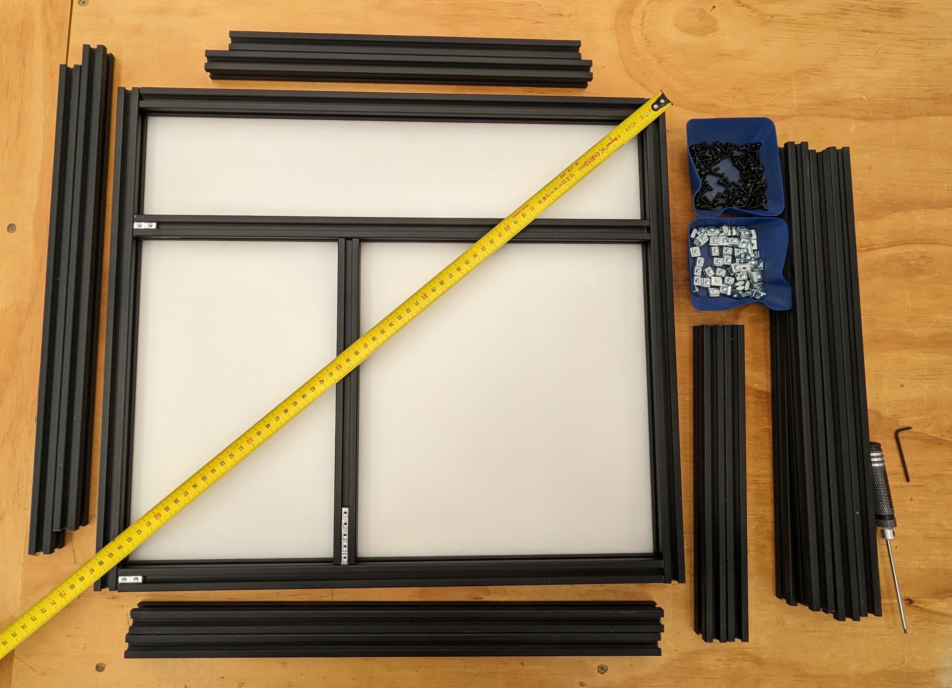
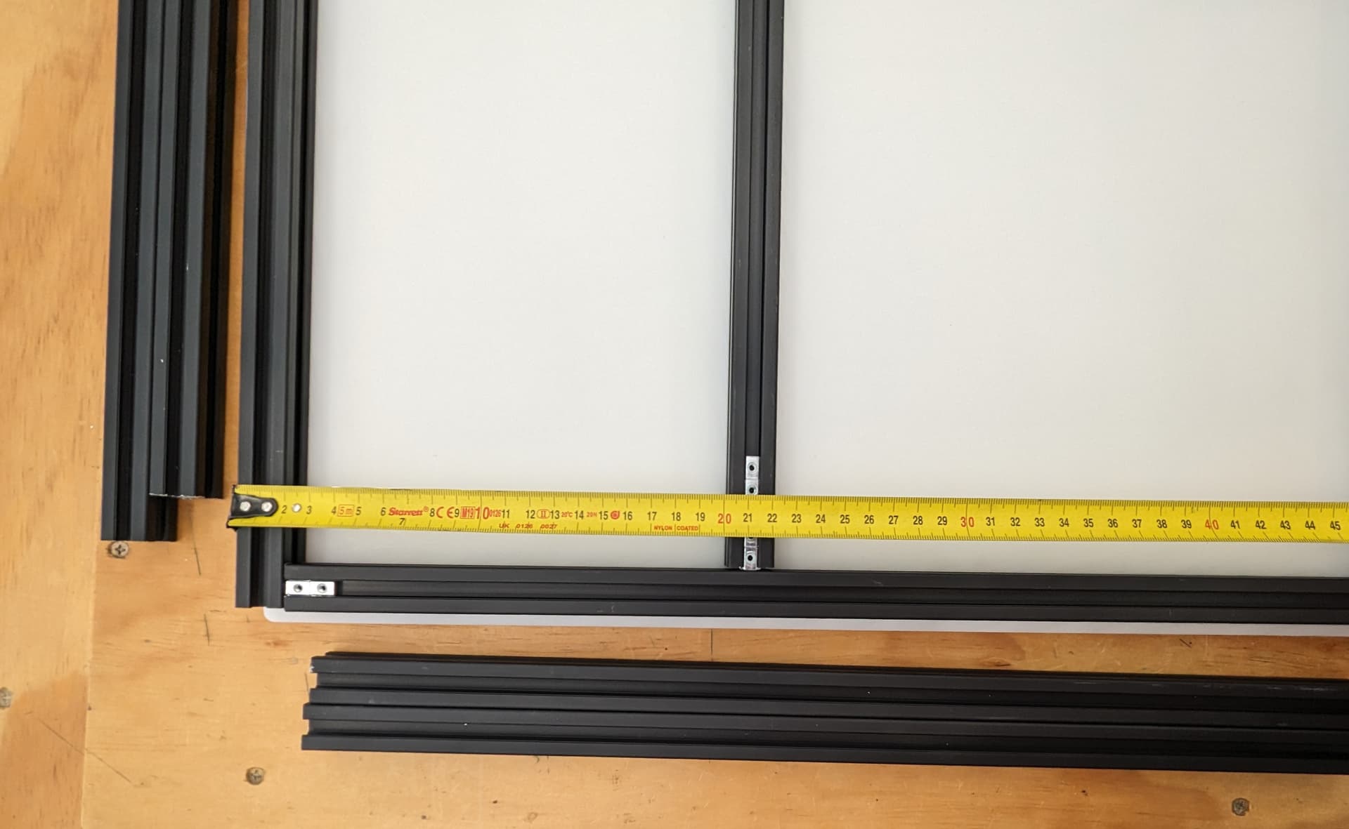
Verify Z rail location to the CAD dimensions. Do yourself a favor and get them all very accurate.
Build out the side panels, stop at this point to load in trapped T Nuts.
Verify verify dims
Load in the Nuts for attaching the sides
You can slide the sides in to get ready for the bottom.
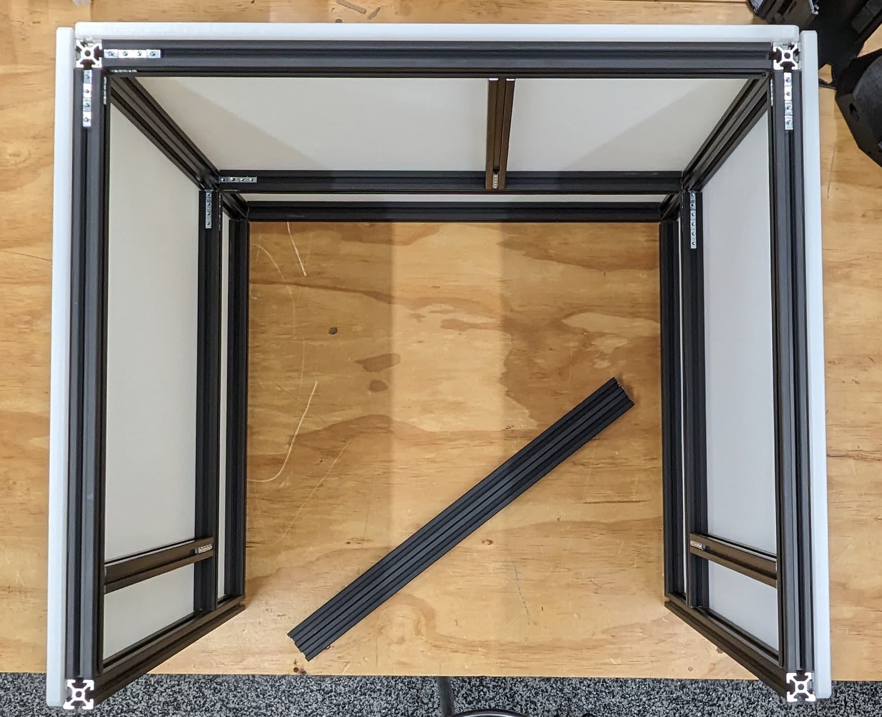
Add the front bottom rail to the bottom panel.
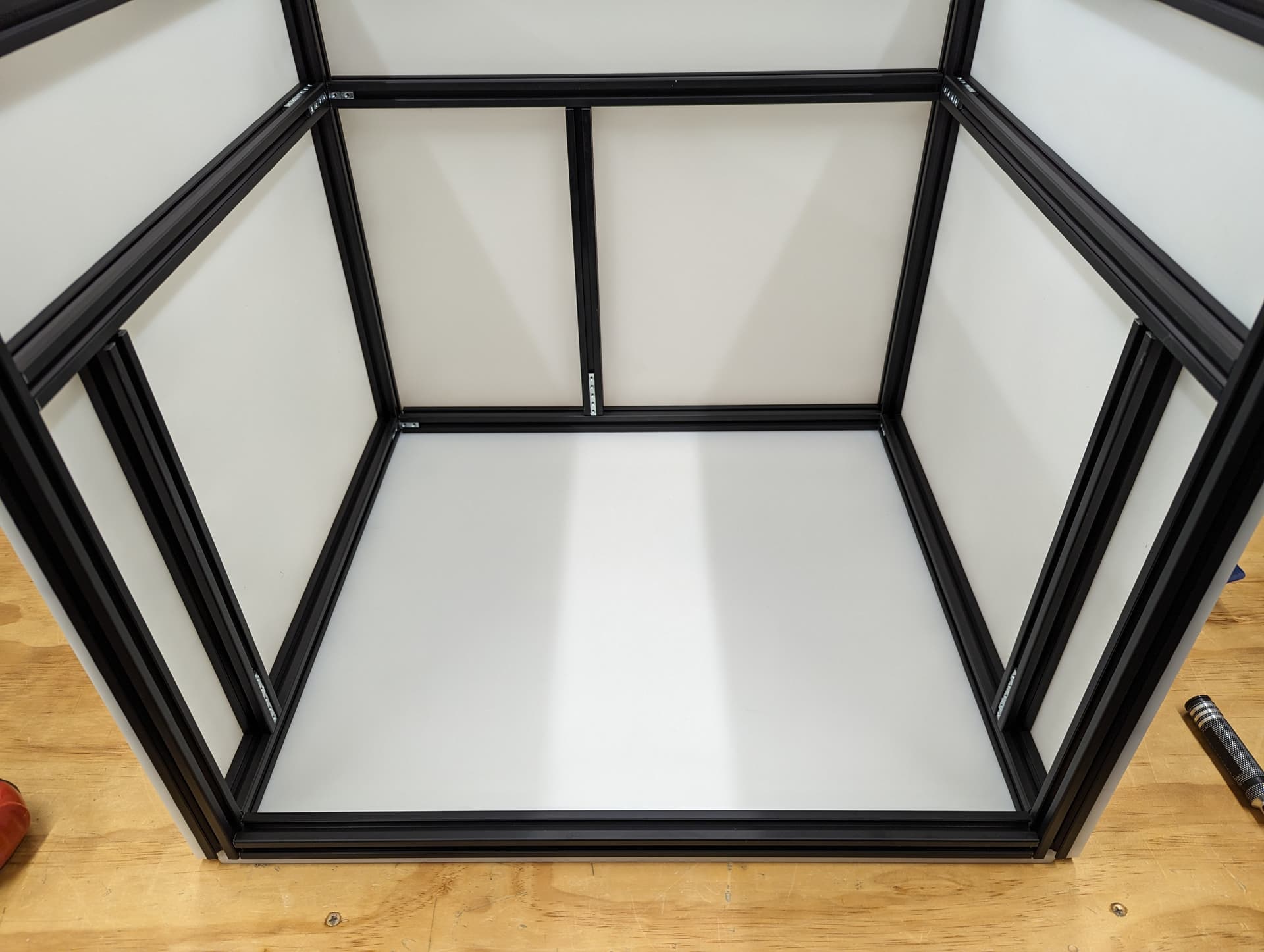
Attach the bottom and check all the dimensions again, snug up the screws. Check every diagonal you can. I stop here to add the hardware in while it is easy to reach in. If you are building a corner bracket frame feel free to build the whole cube.
Z Belt
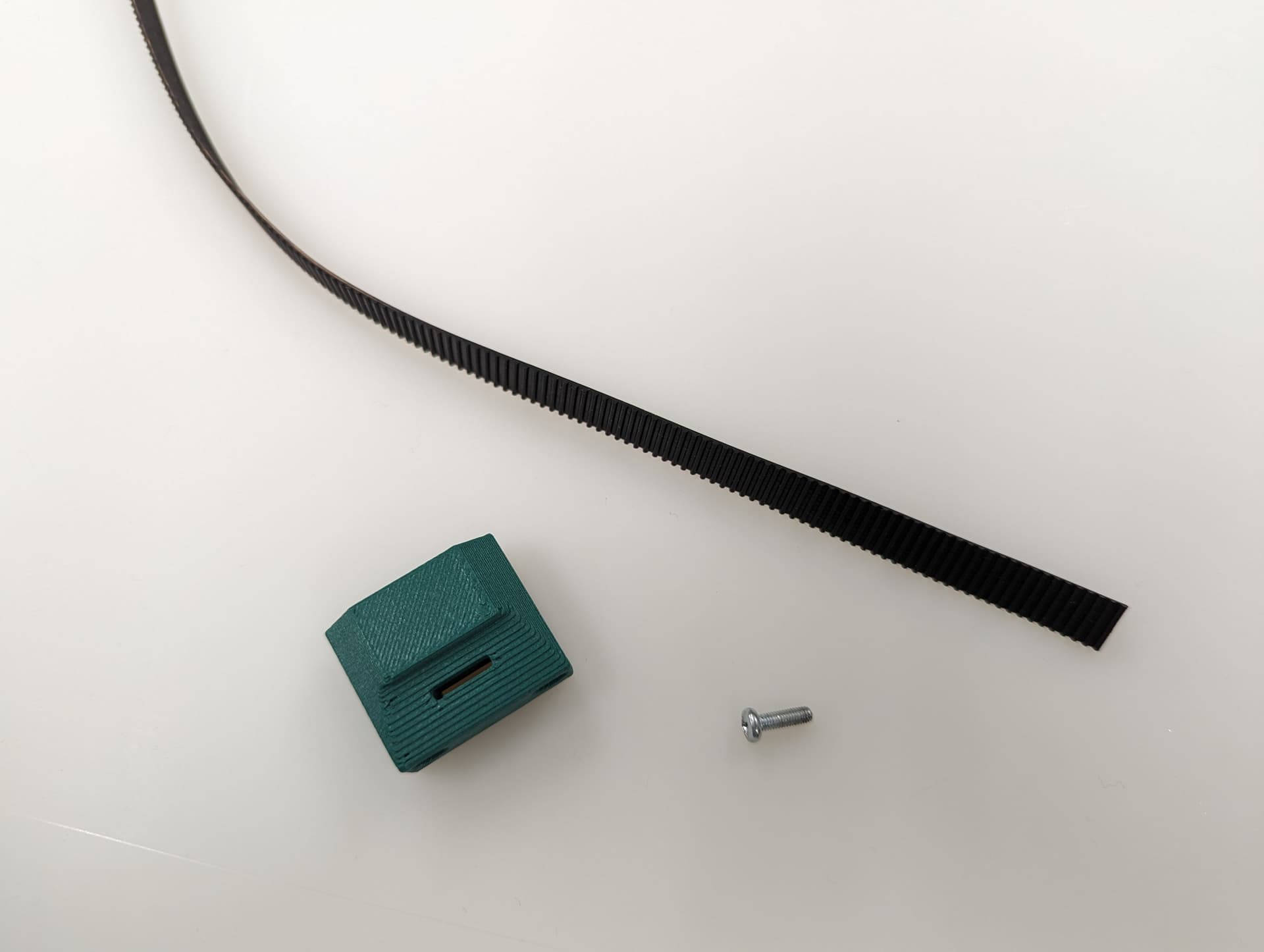
Parts required for this step
| QTY | Name |
|---|---|
| 3 | Z Belt Lower |
| QTY | Name |
|---|---|
| 9 | M3x10mm screws |
| 6 | M3 t-nuts |
Assembly
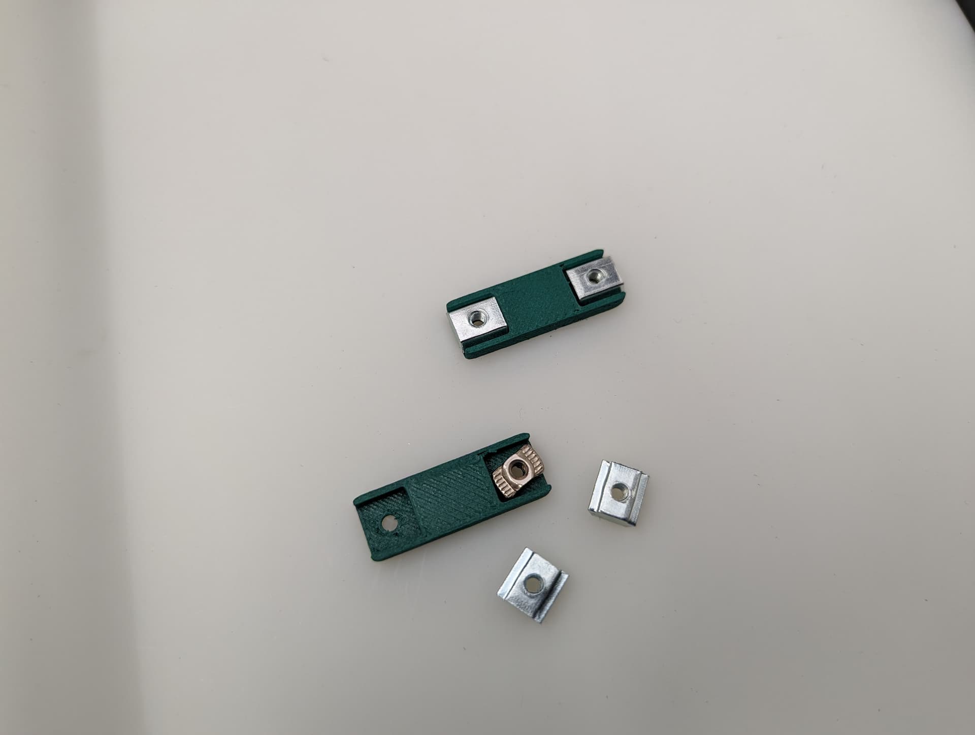
This is a new style of fastening. Using a M3x8mm screw, you can easily and securely anchor the belts
Get the belt started, you don’t need to it be as big of a loop as this picture, but do what is easy for you. This will be trimmed later.
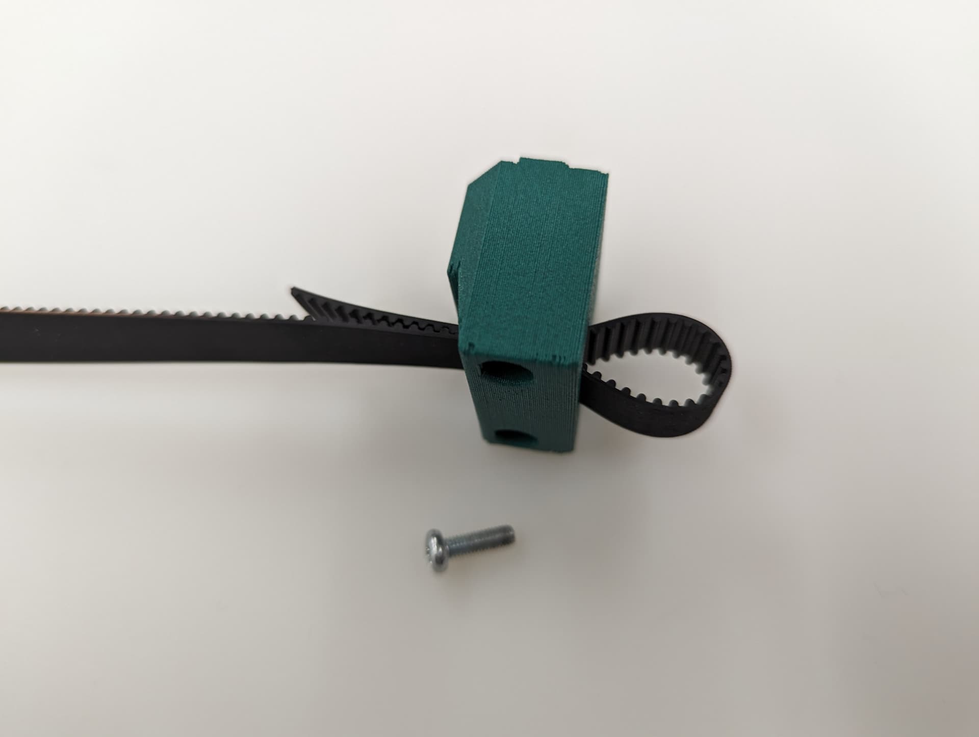
You will see there is a slightly larger opening on one side for the head of the fastener.
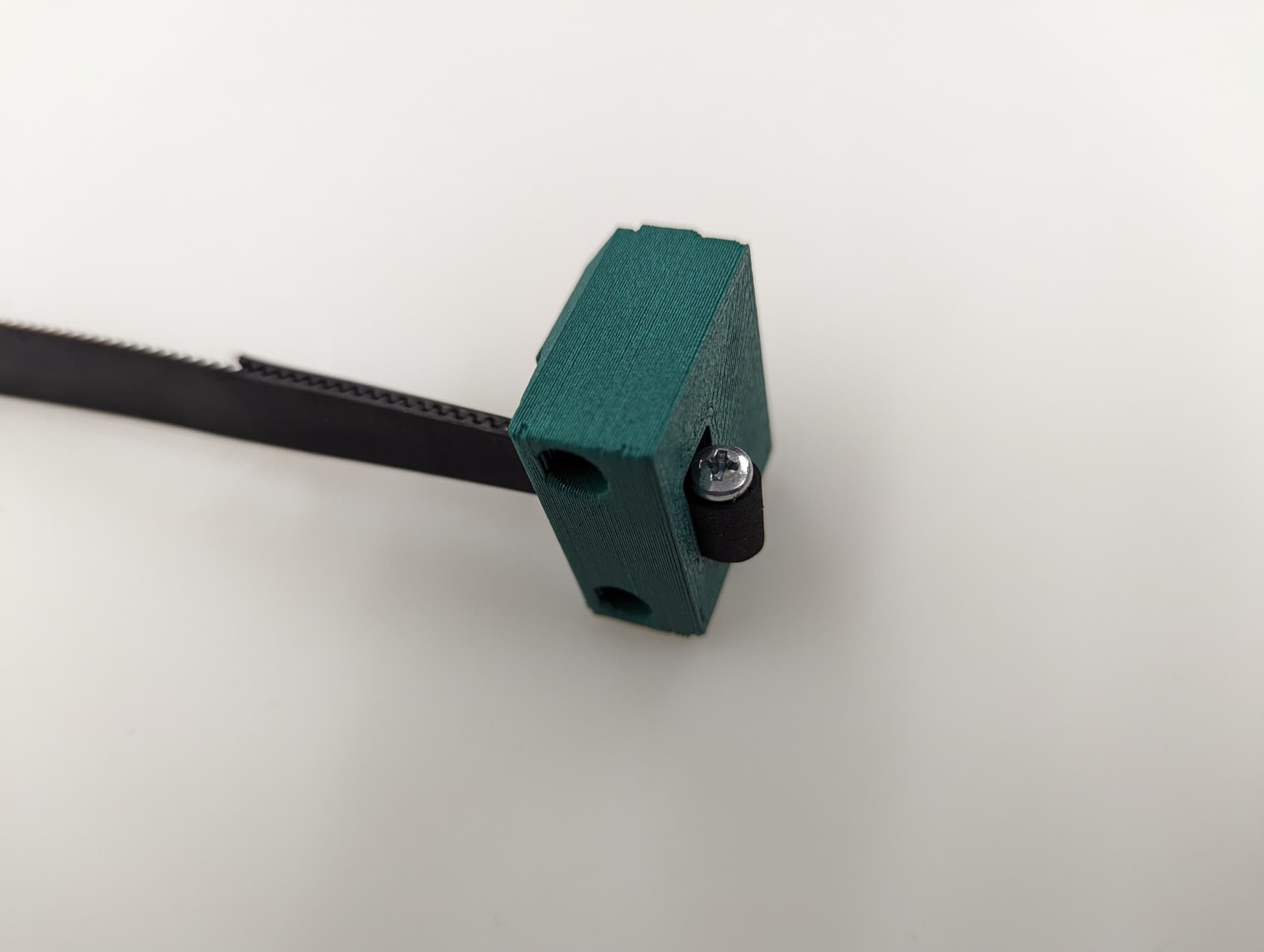
Pull it all the way in nice and tight.
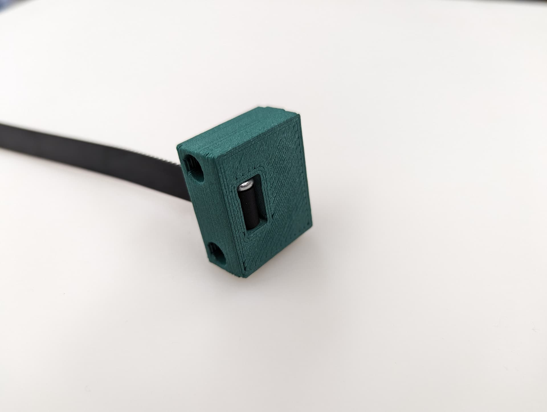
Trim the belt off, make sure it is not too far over the top of the block.
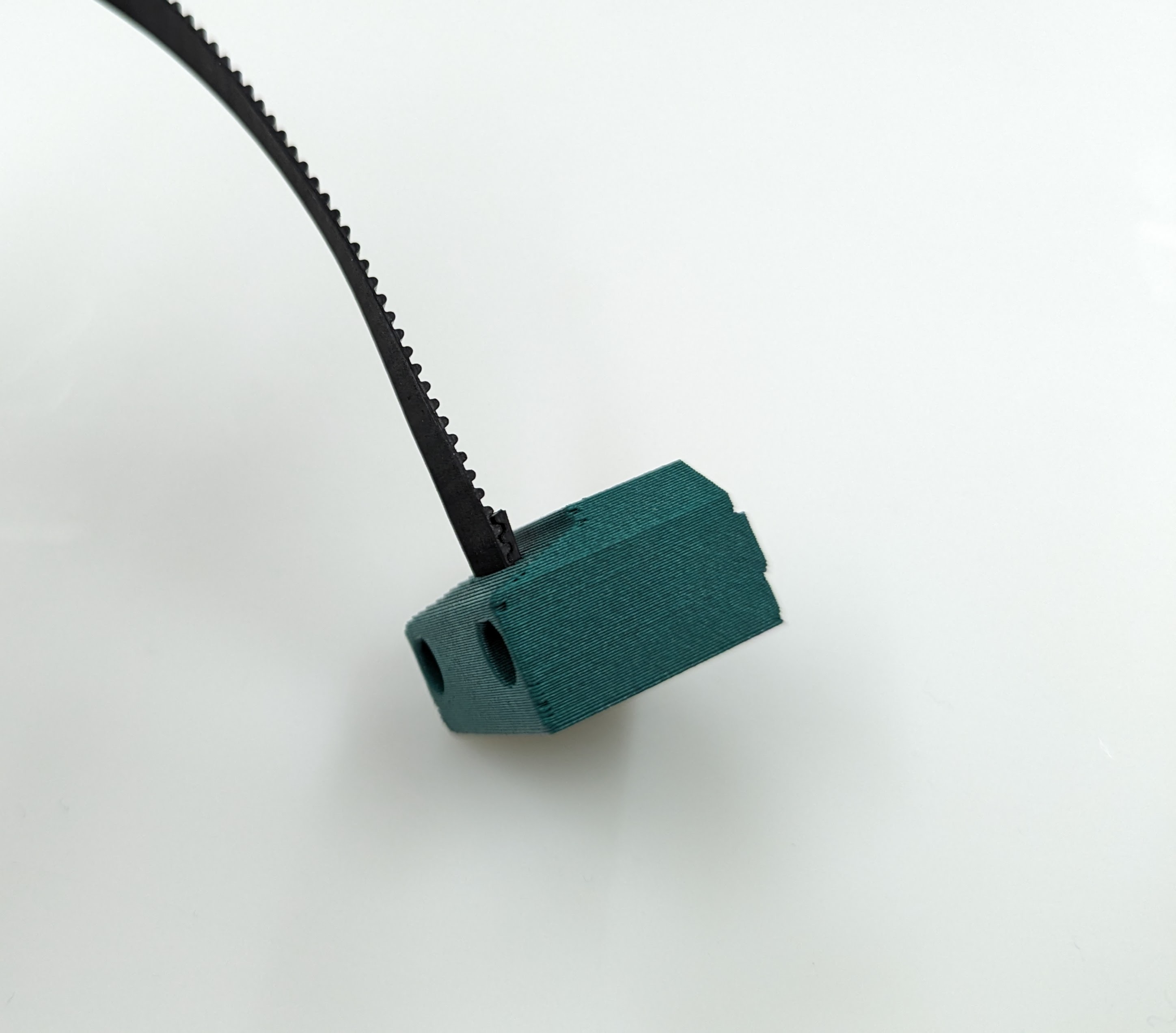
Get the belt ready for the rest of the Z axis.
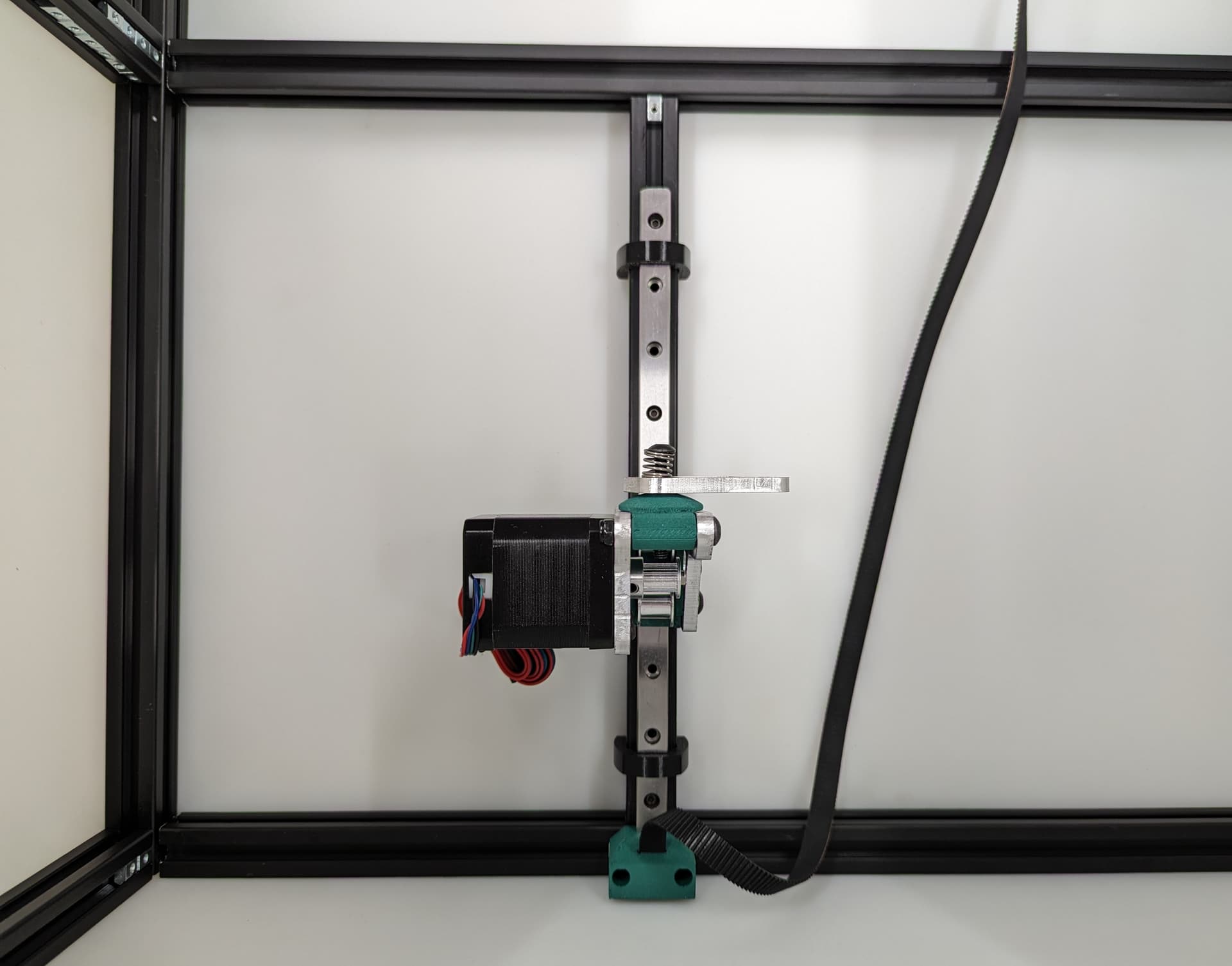
Z Axis
The next step will be to assemble and install the motion system for the Z axis.
Note
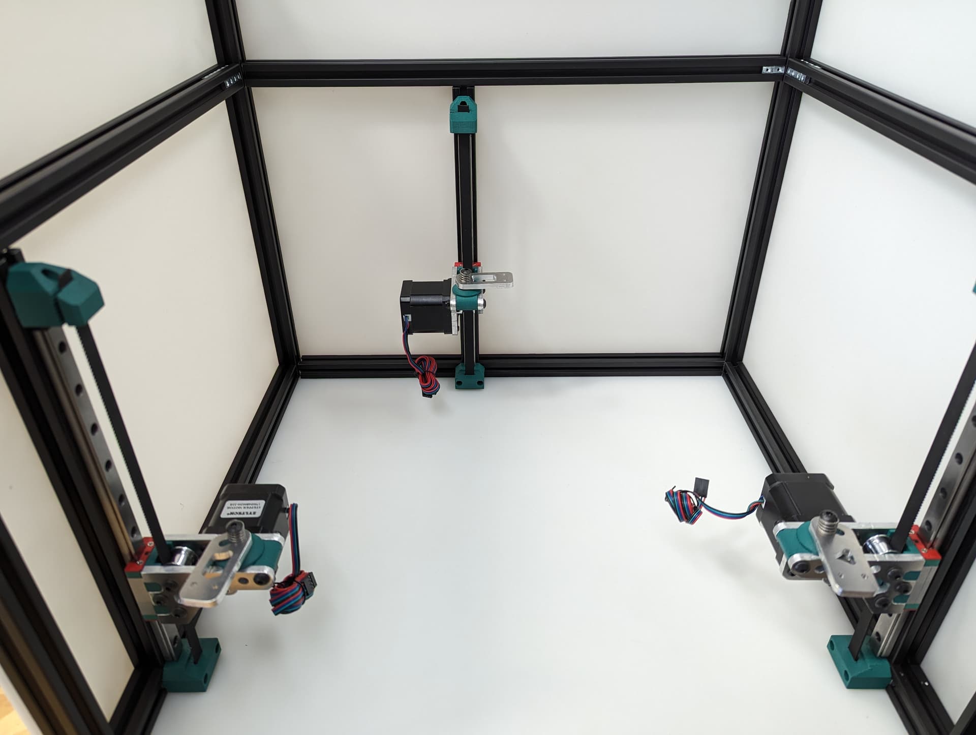
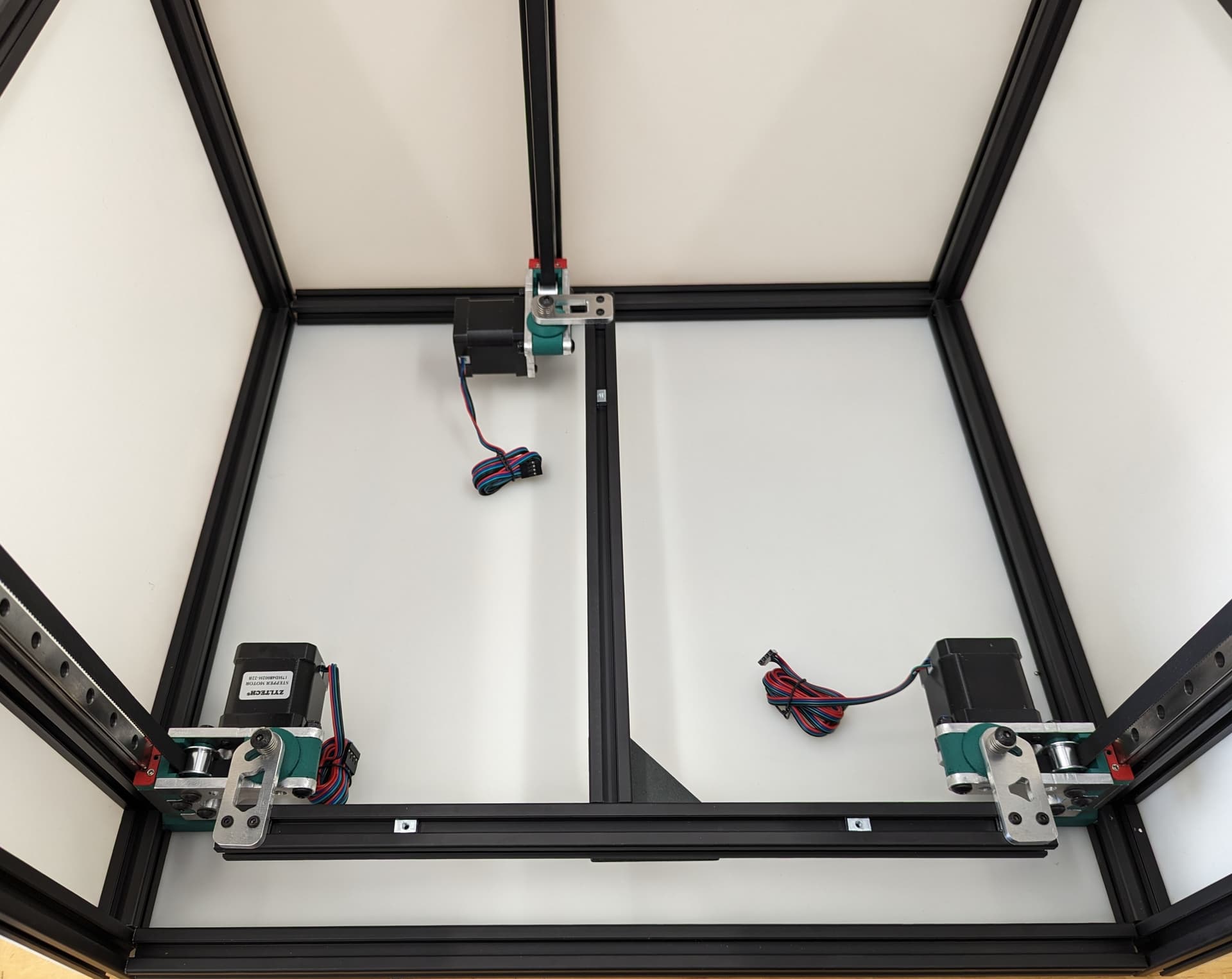
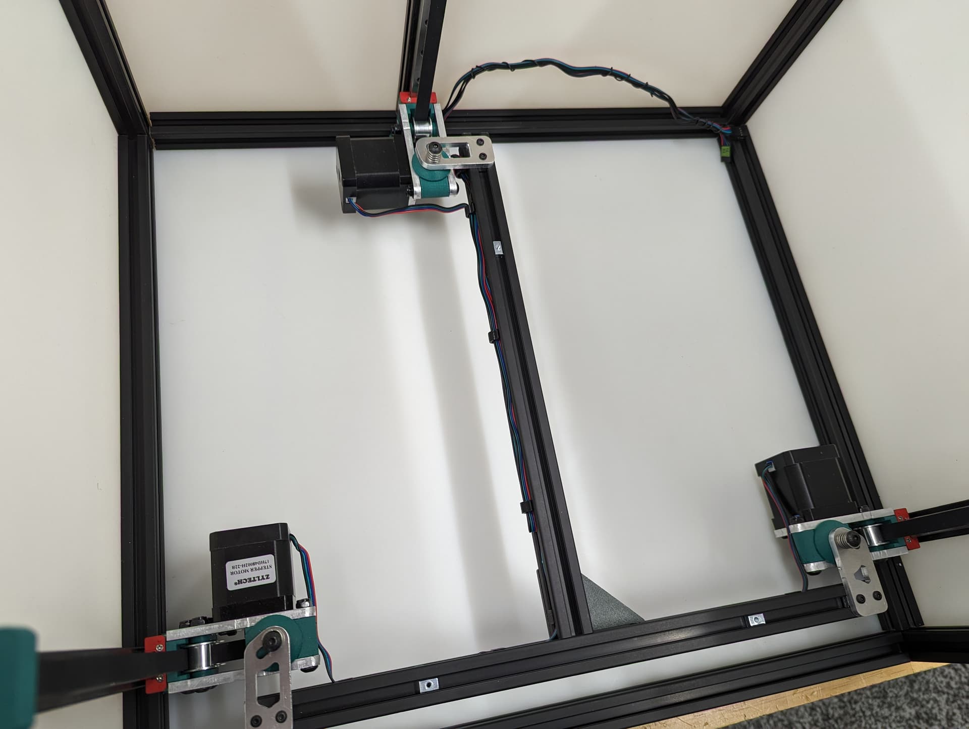
Pay close attention while installing to the orientation of stepper motors. The 3 axes are NOT all assembled exactly the same.
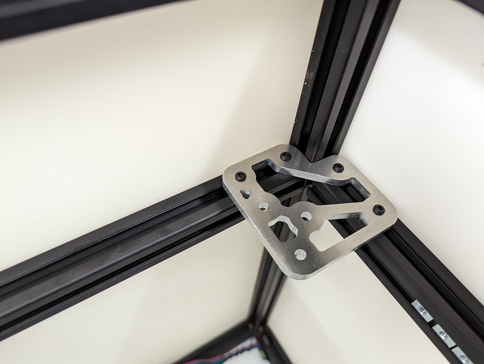
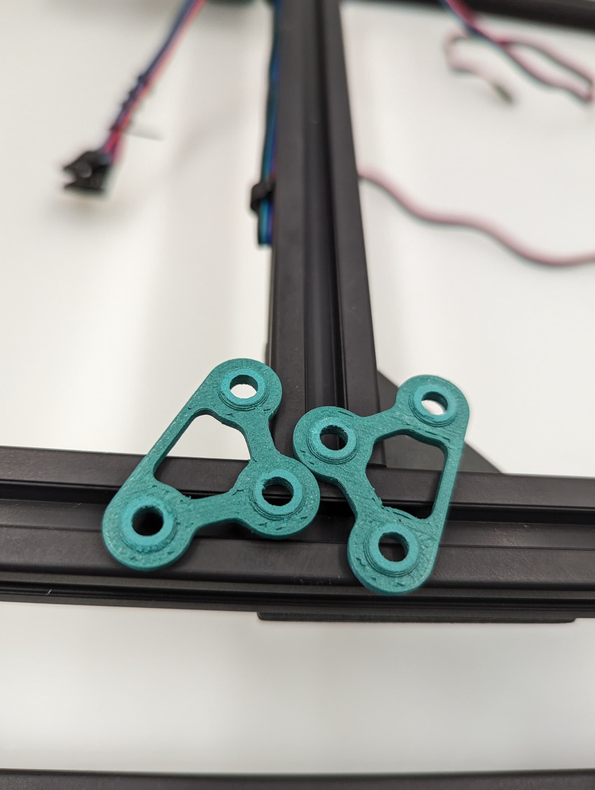
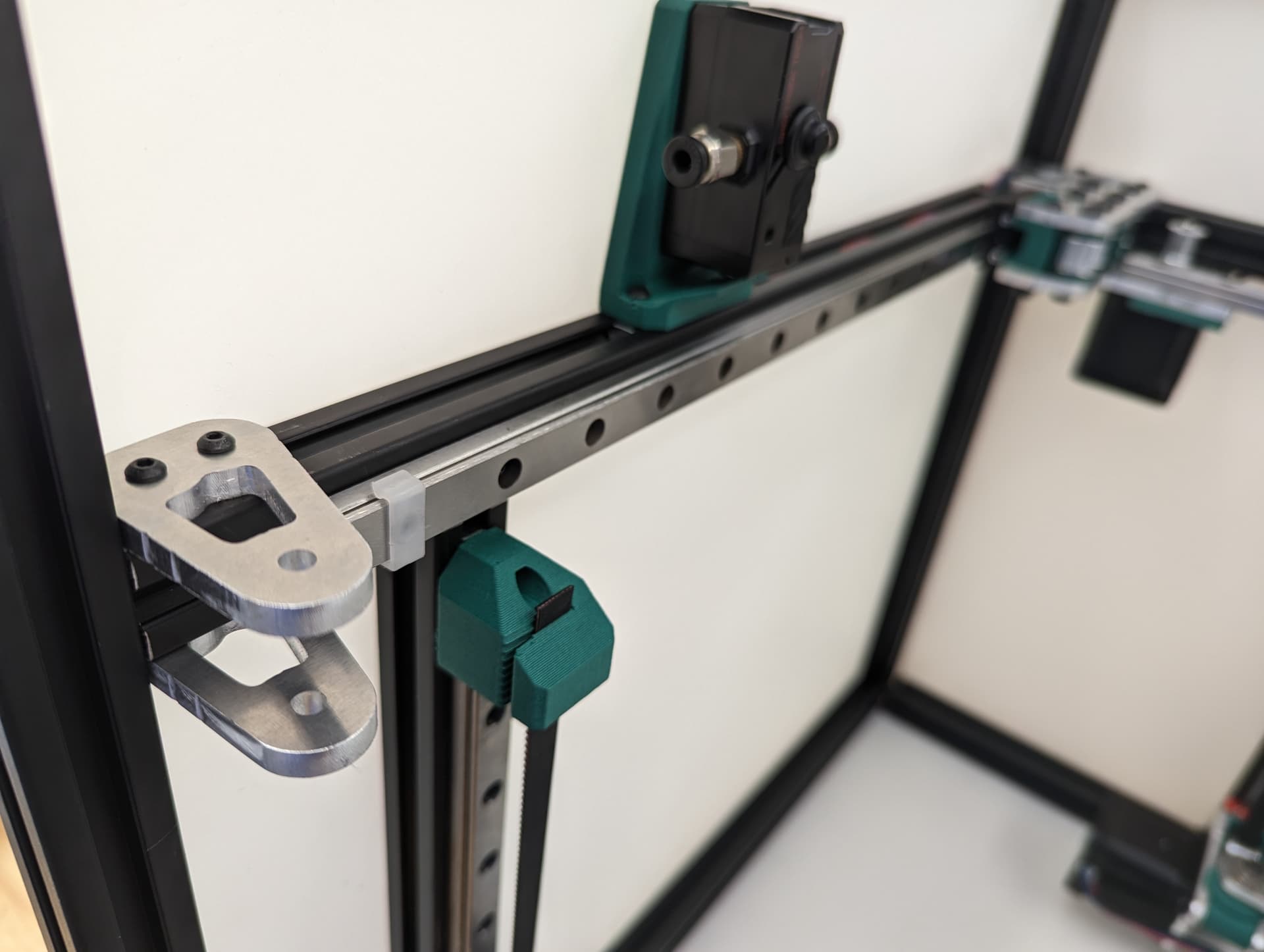
The 3 bed mount plates are also not the same, and orientation matters. Make sure your placement matches the picture below. Pay attention to the shape of the holes in each plate
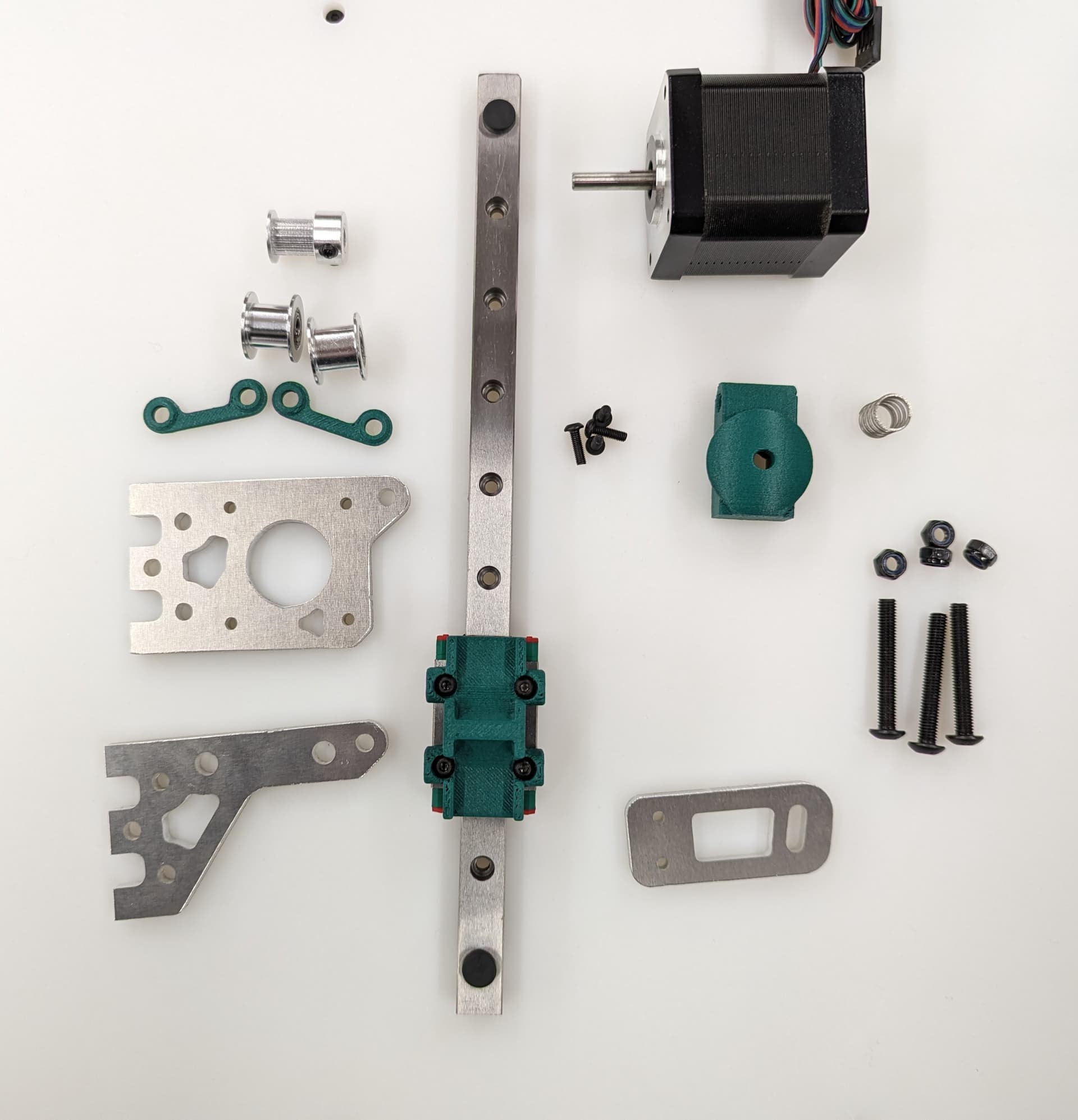
The final result will look something like this.
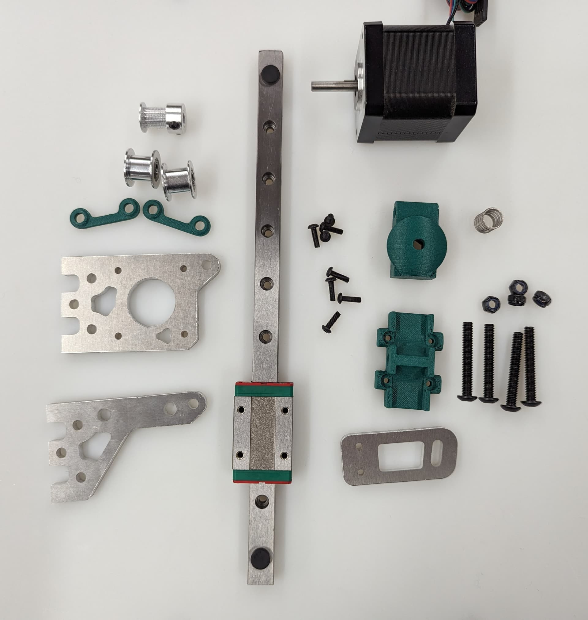
Parts required for this step
| QTY | Name |
|---|---|
| 4 | Z Front |
| 3 | Z Back |
| 1 | Bed A |
| 1 | Bed B |
| 1 | Bed C |
| QTY | Name |
|---|---|
| 3 | Z Stepper - Bed Mount |
| 6 | Z Stepper - Z spacer |
| 3 | Z Belt Upper |
| 3 | Z Stepper - Z Bearing Mount |
| QTY | Name |
|---|---|
| 8-12 | M3x8mm screws |
| 4-8 | M3 t-nuts |
| 4 | M5x35mm screws |
| 4 | M5 locknuts |
| 4 | M3x10 screws |
| 3 | Bed Spring |
| 3 | Stepper Motor |
| 3 | Z Linear Rail |
| 6 | Smooth Idler |
| 3 | Pulley |
Assembly
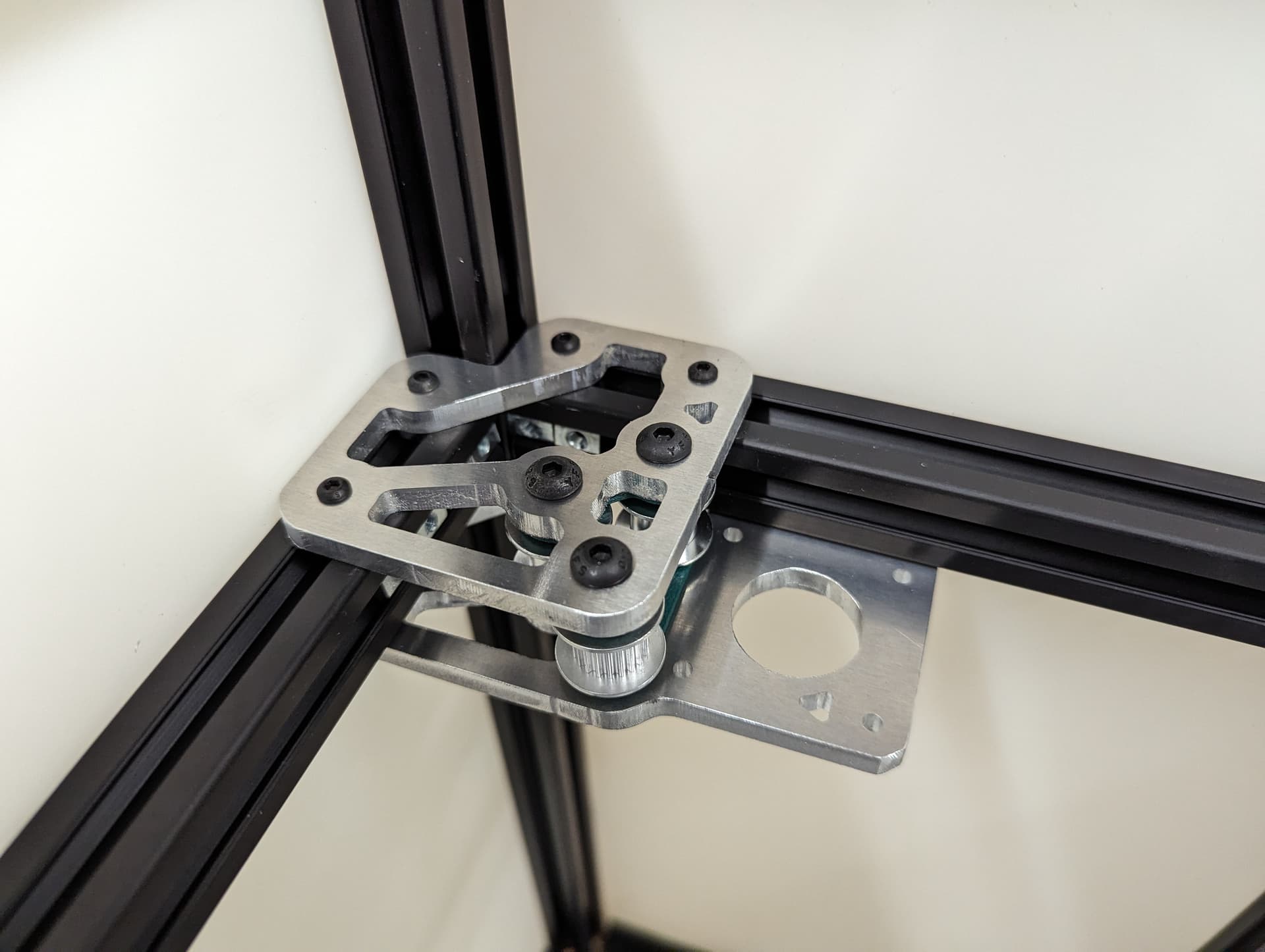
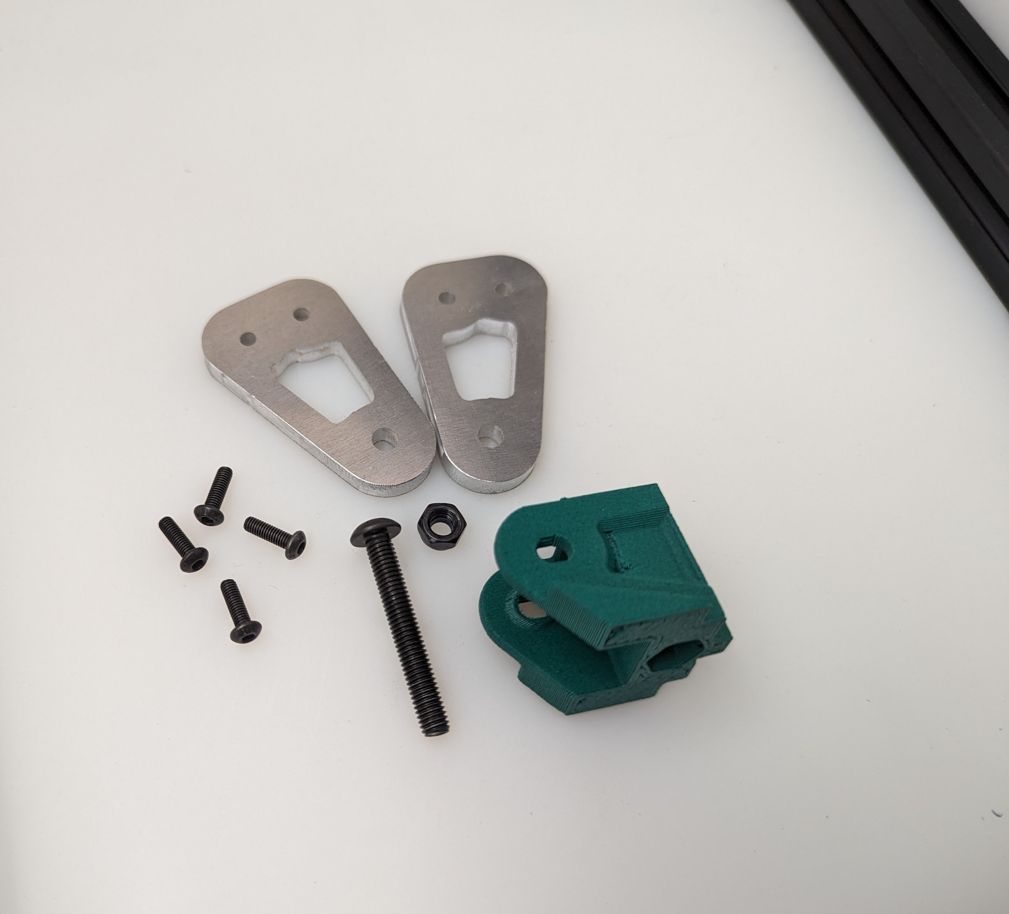
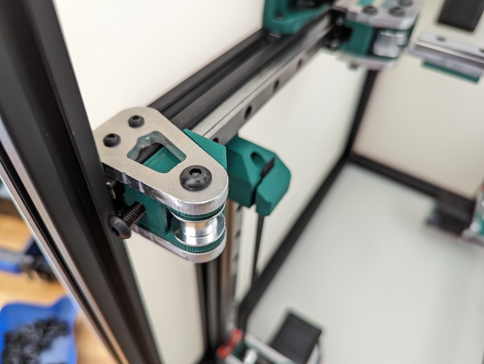
Start by installing the Z Truck to the Rail block with 4 M3x10 screws
Add the 2 side plates to the Z truck. Make sure the plates are oriented correctly for the corresponding axis you are working on according to the picture above. This step is what sets the direction.
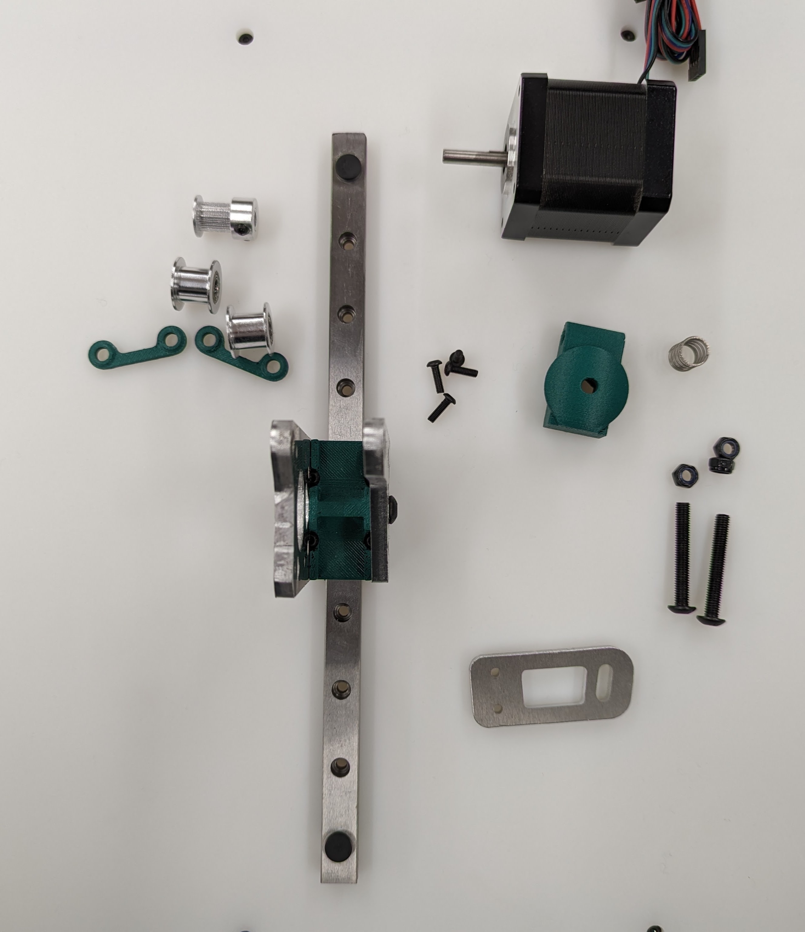
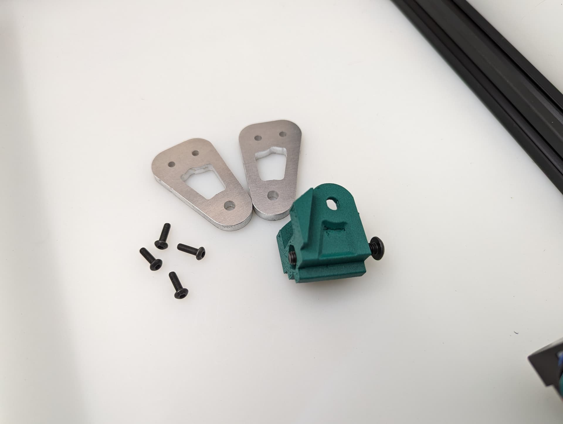
Add the bed mount between the plates and secure with a M5x35 Screw and locknut.
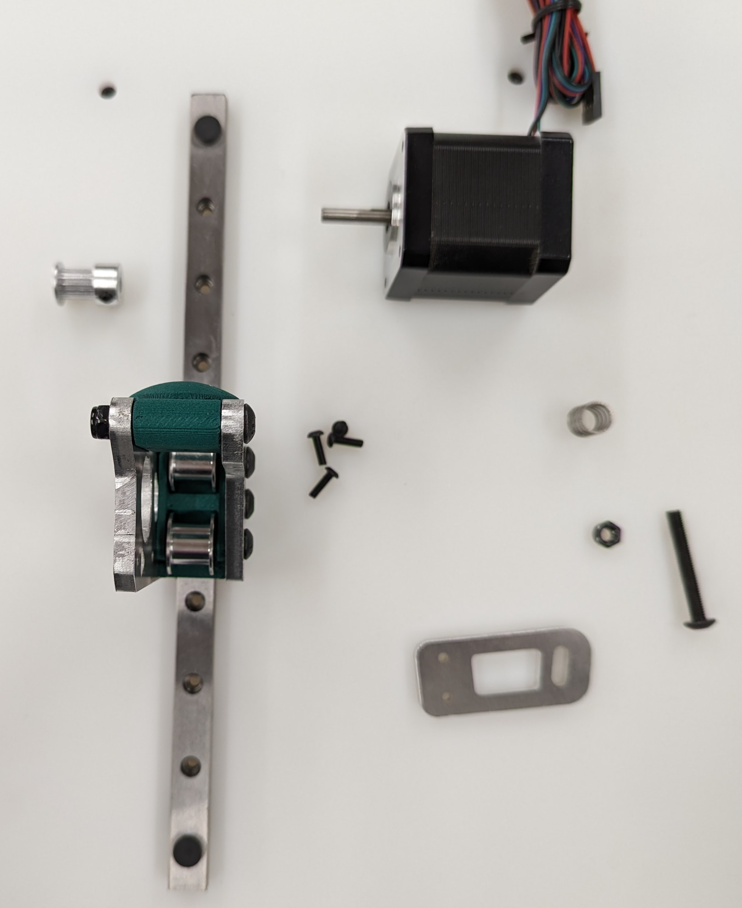
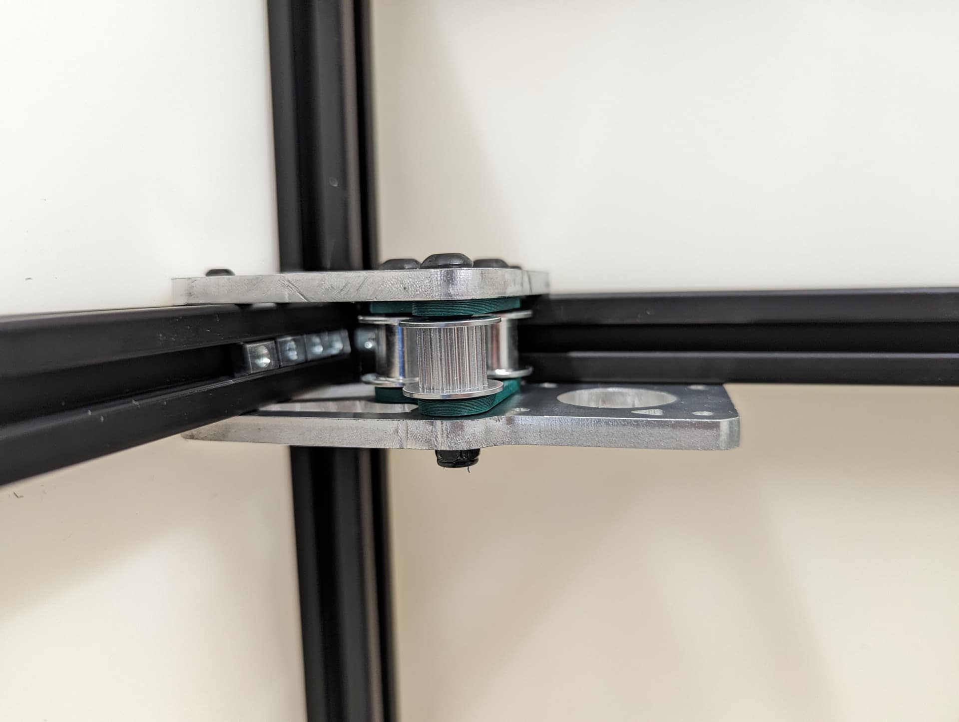
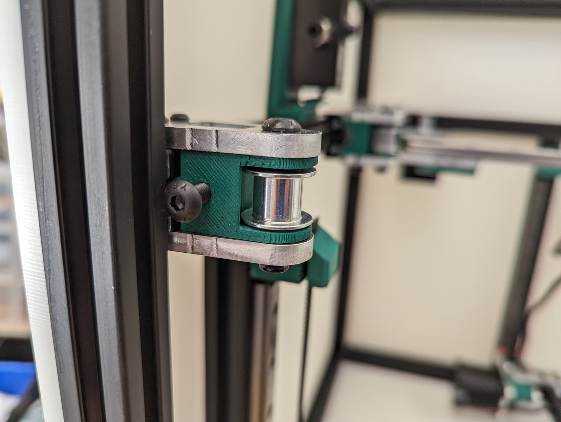
Add your idlers and spacers to the assembly M5x35 screws and locknuts. Make sure the idlers are not squished. You need some play here.
Tip
Feel free to lightly sand the spacers to give more room if needed.
If the M5 screw does not easily slide into the spacer, use a drill bit to open the hole up a little. The spacer needs to be able to slide without grabbing on to the screw.
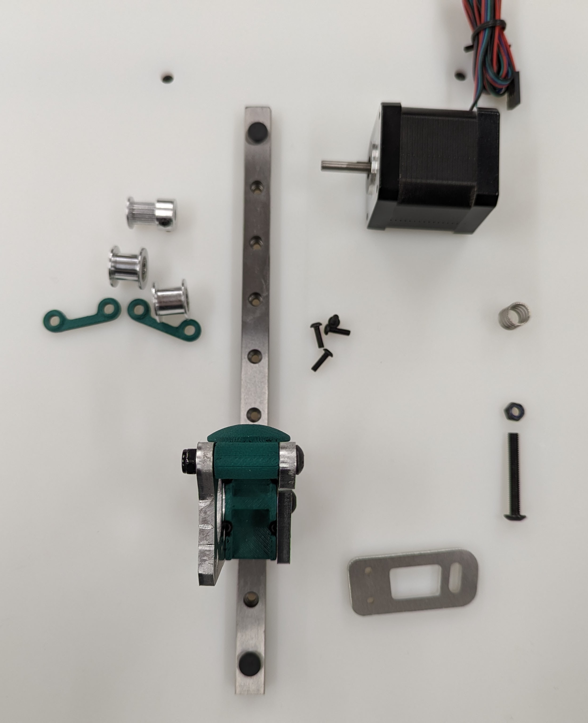
Add the bed mount plate and “spring” to the assembly using a M5x35 screw and locknut.
The locknut here is a captured nut. Insert the nut into the hole as far possible to ensure it will grab. Careful not to over-tighten.
Warning
Be sure you have the correct bed mount plate for the axis you are working on. Orientation Matters!!
See final assembly picture above to verify.
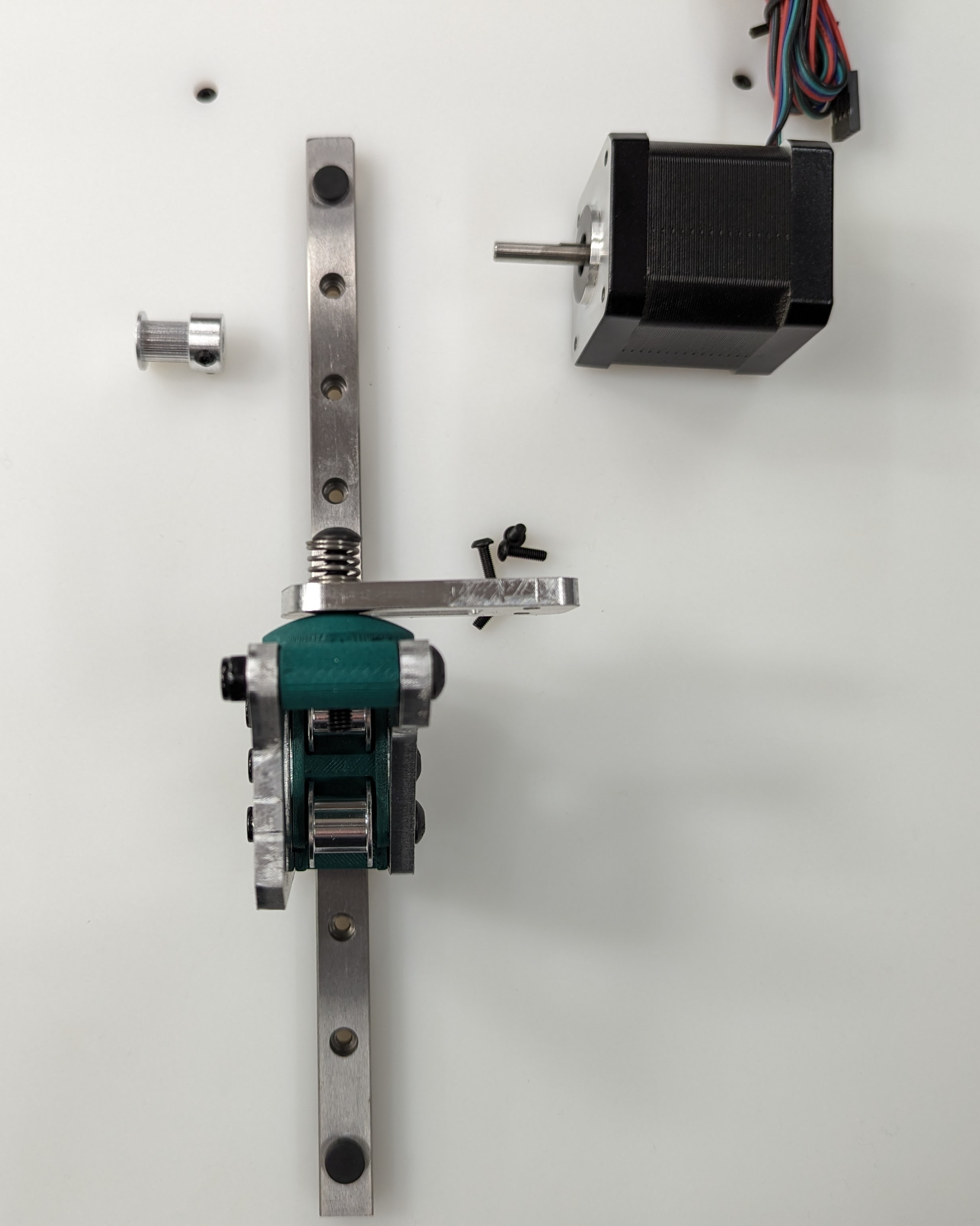
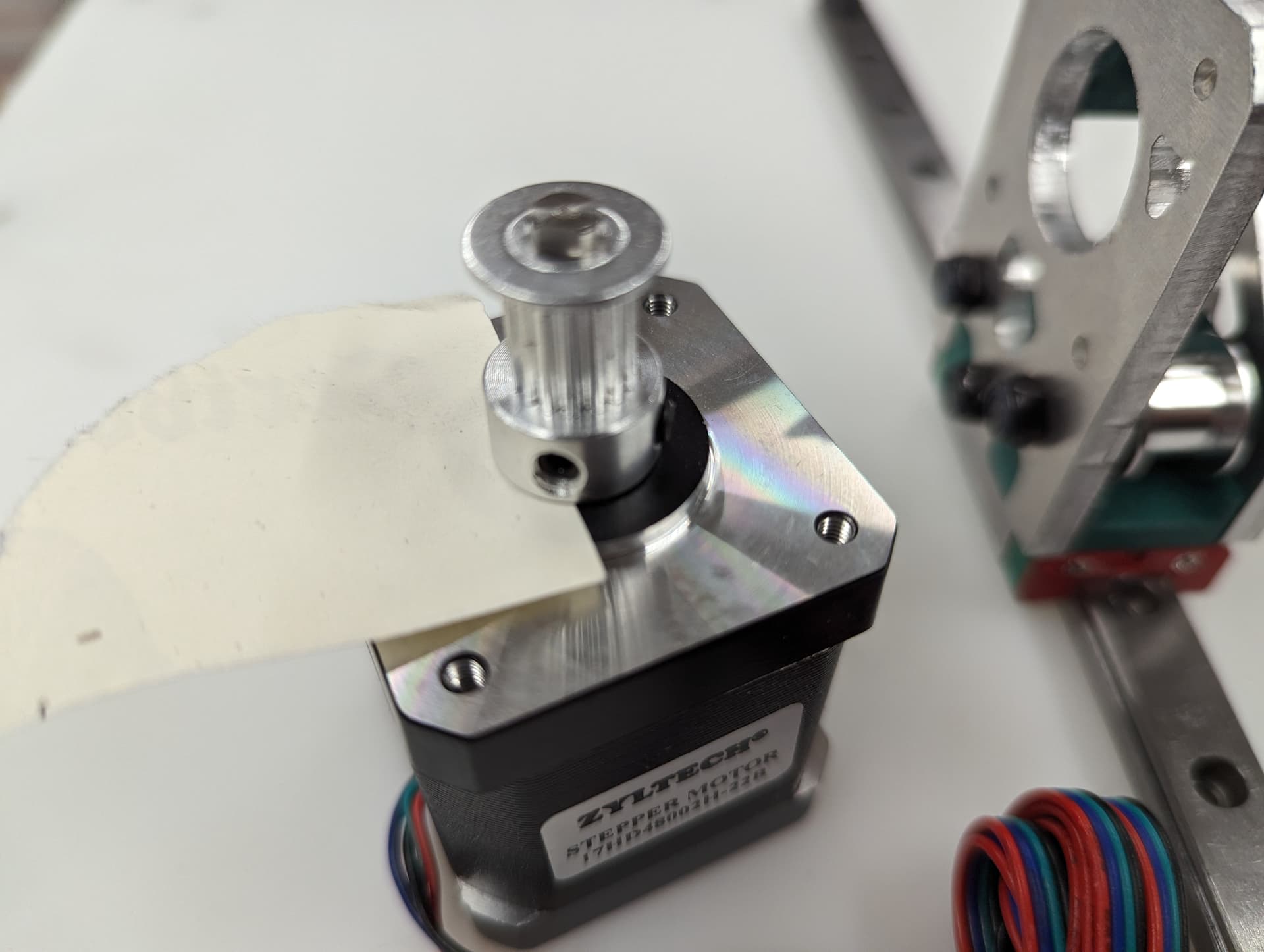
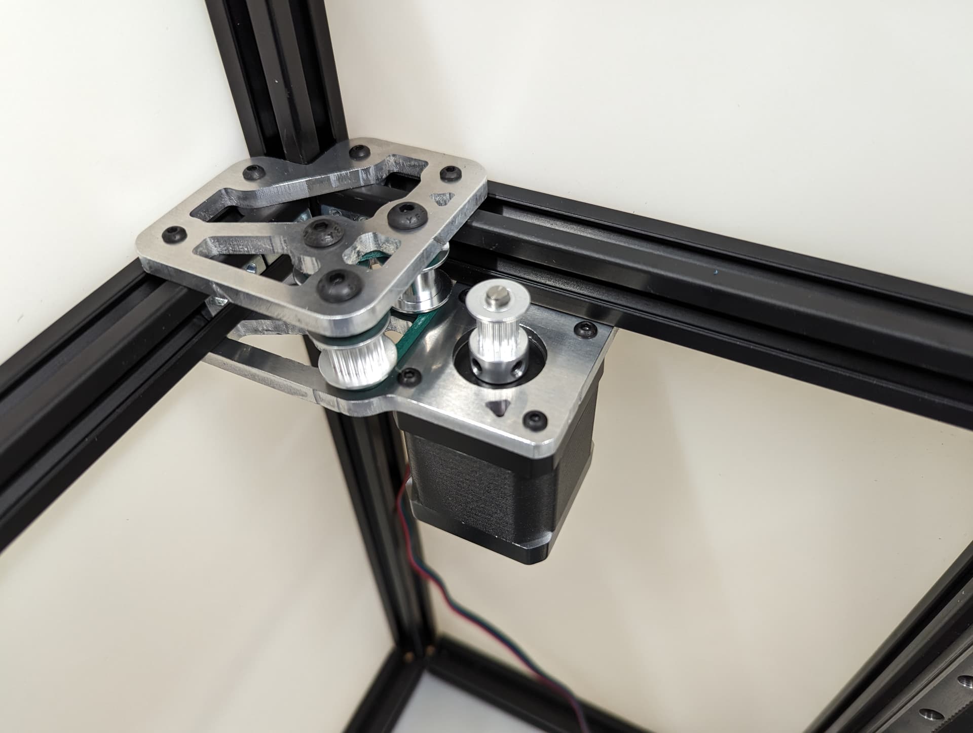
Add the pulley to the stepper motor shaft. A sheet of paper is an ideal spacer for pulley placement.
Tip
Use of thread locker on the set screws is highly recommended here
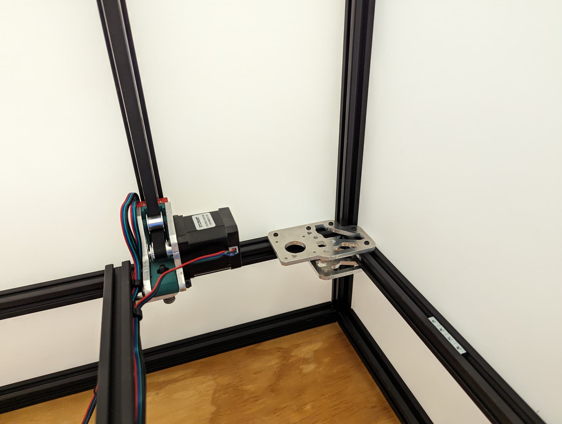
Add the stepper motor to the mount plate with 4 M3x8 screws. Pay attention to wire orientation. Wires facing to the middle allow for easiest wire routing later.
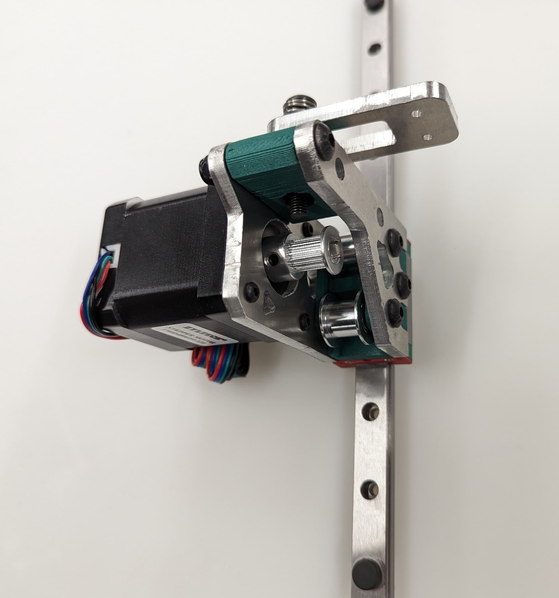
Now is a good time to check that the pulley and idlers are in line with each other
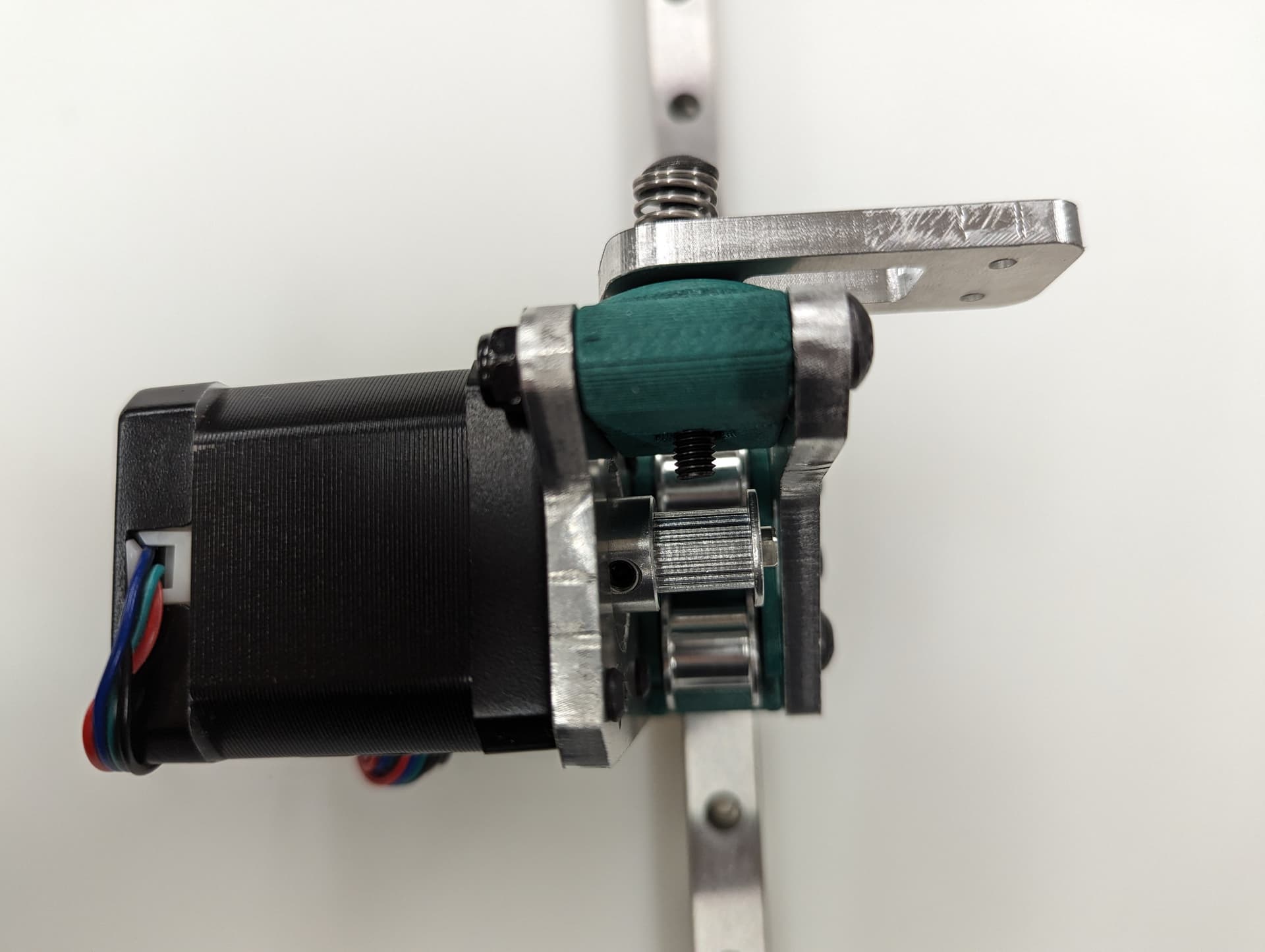
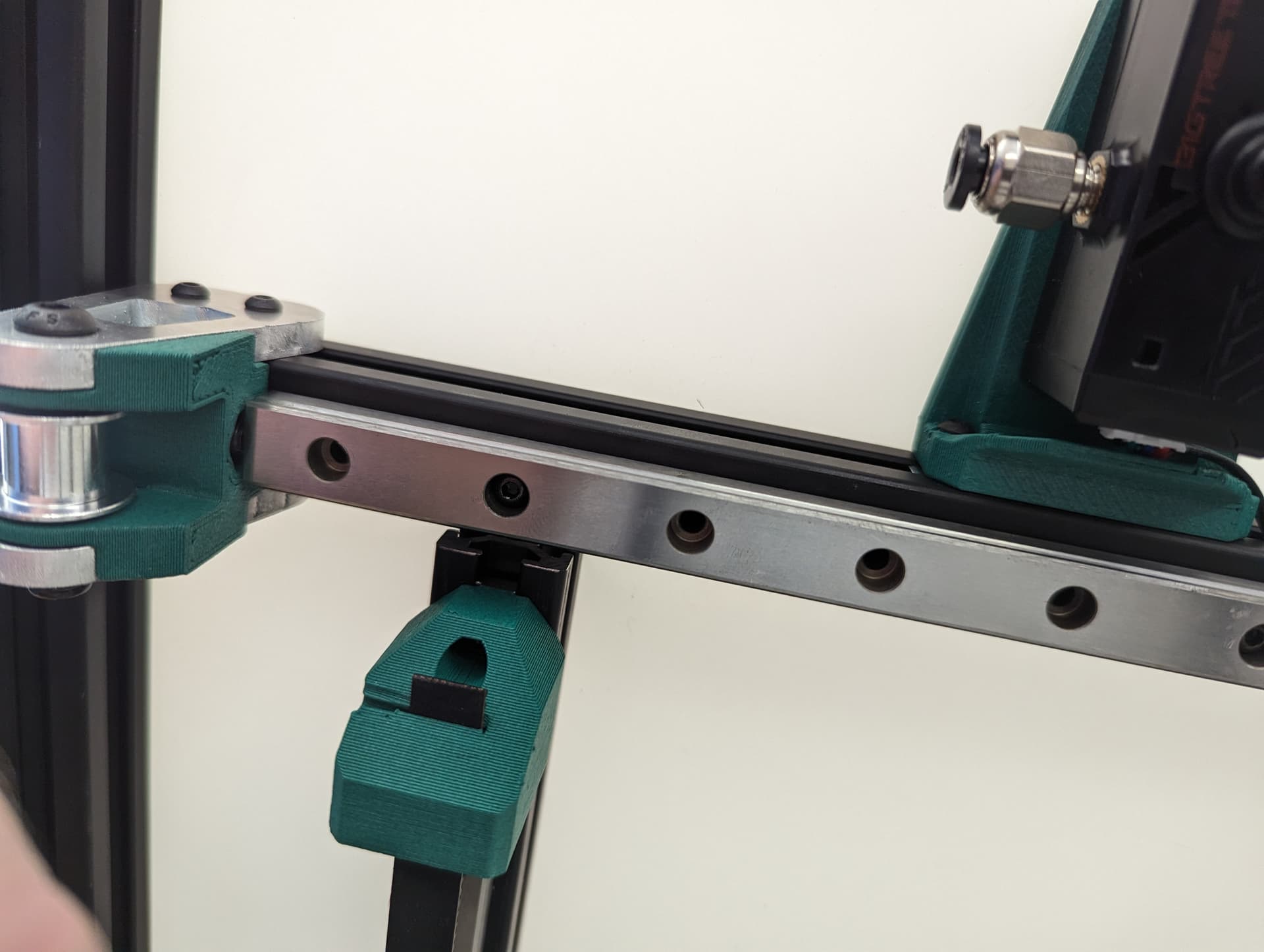
Center your rail on the extrusion, and line up your t-nuts. The Z Rail should be touching the lower belt mount.
Snug the rail on with M3x8mm screws.
Tip
Use of rail aligners are highly recommended here. You can print a few yourself from Printables - Rail Aligner.3mf
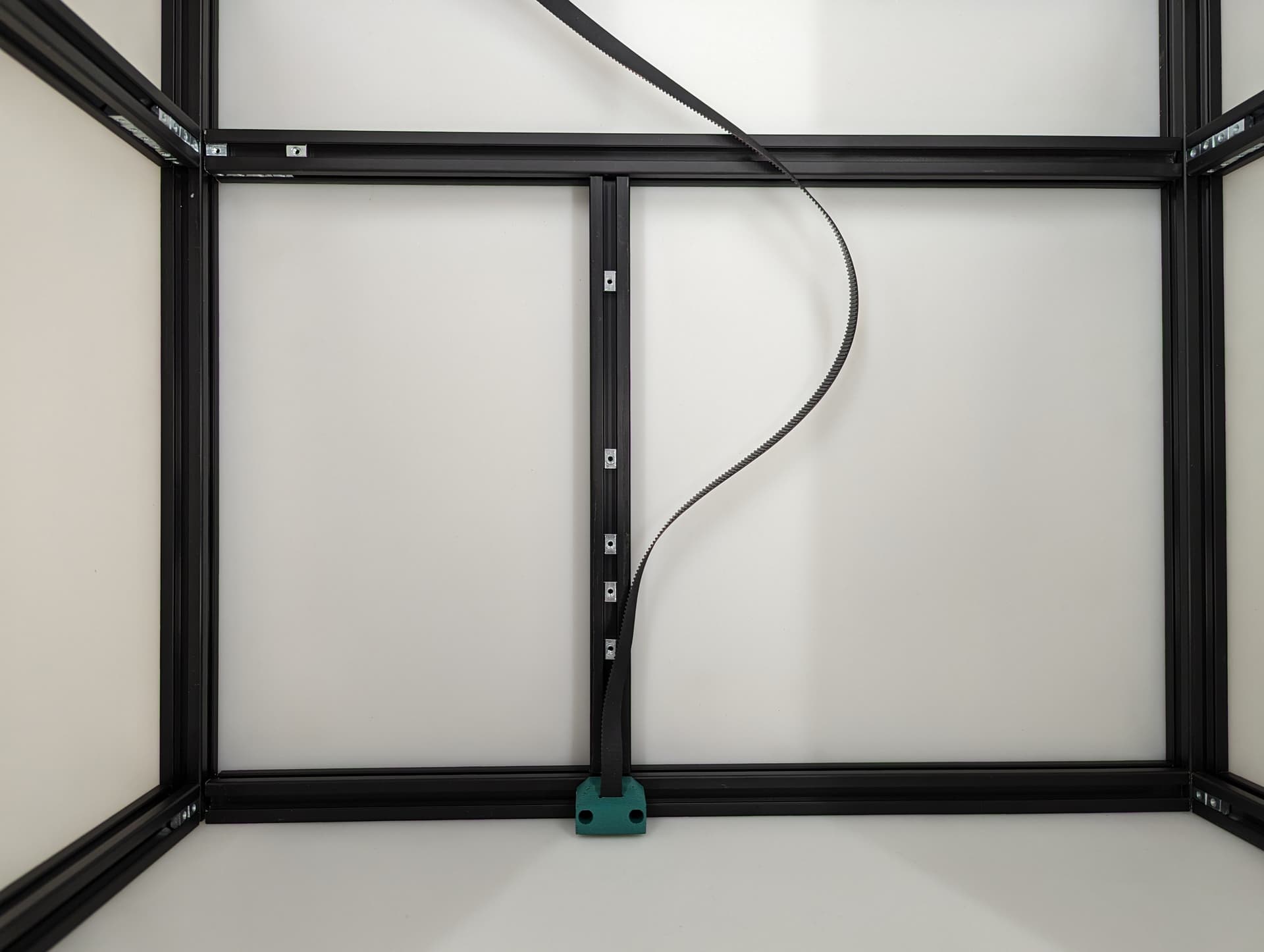
Add the Z Belt upper to the extrusion above the rail using a M3x10mm screw and t-nut
Thread in the belt and add some tension, you should be 2-10mm gap from the top of the rail. The test here is to make sure your Y trucks don’t hit in a later step.
Tip
To tension the belt, loosen the screw on the upper Z mount a little. Push up on the bottom of the mount until the Z belt has tension on it. Tighten the screw back down while holding the tension on the belts.
The Z belts do not need an excessive amount of tension on them.
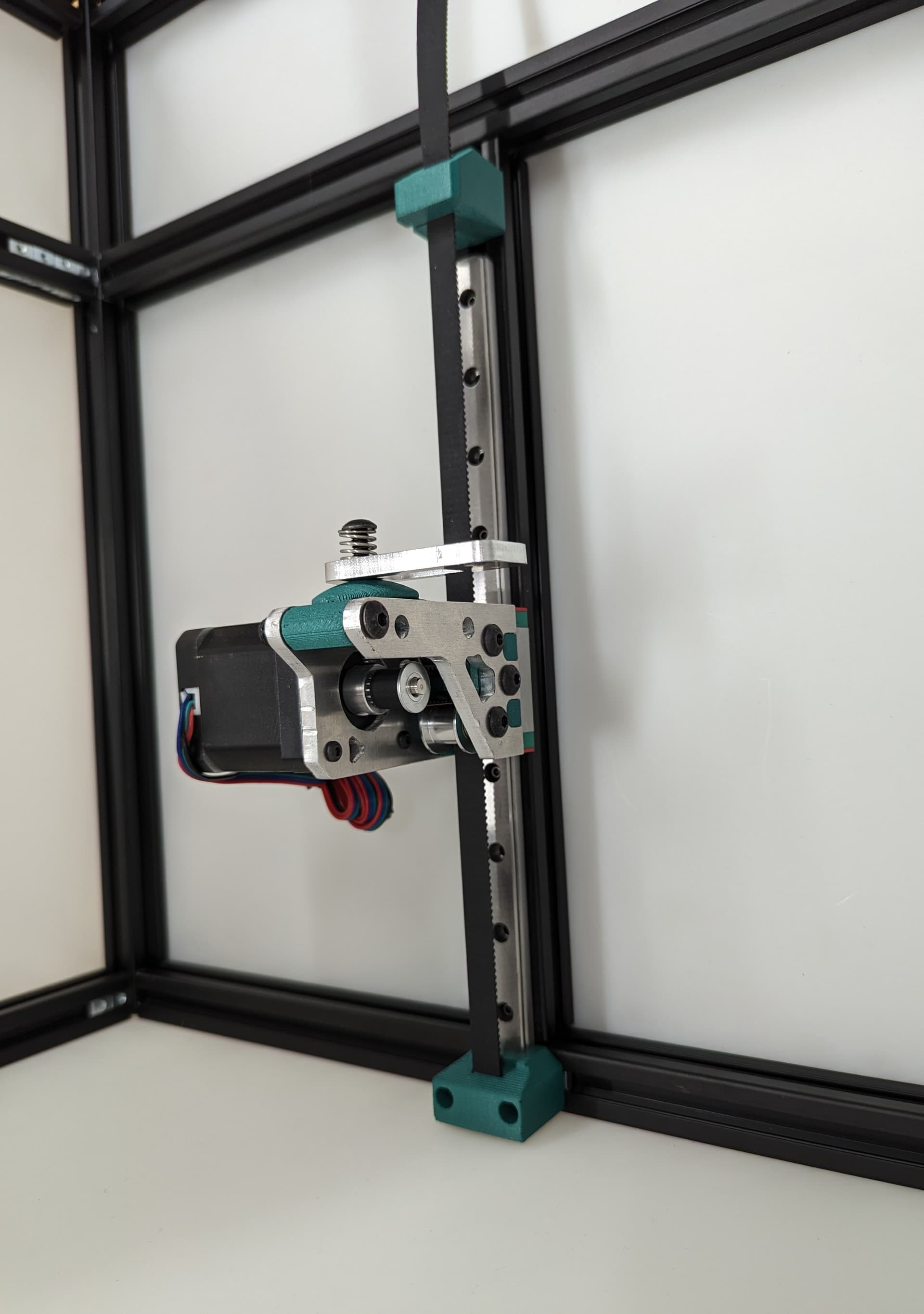
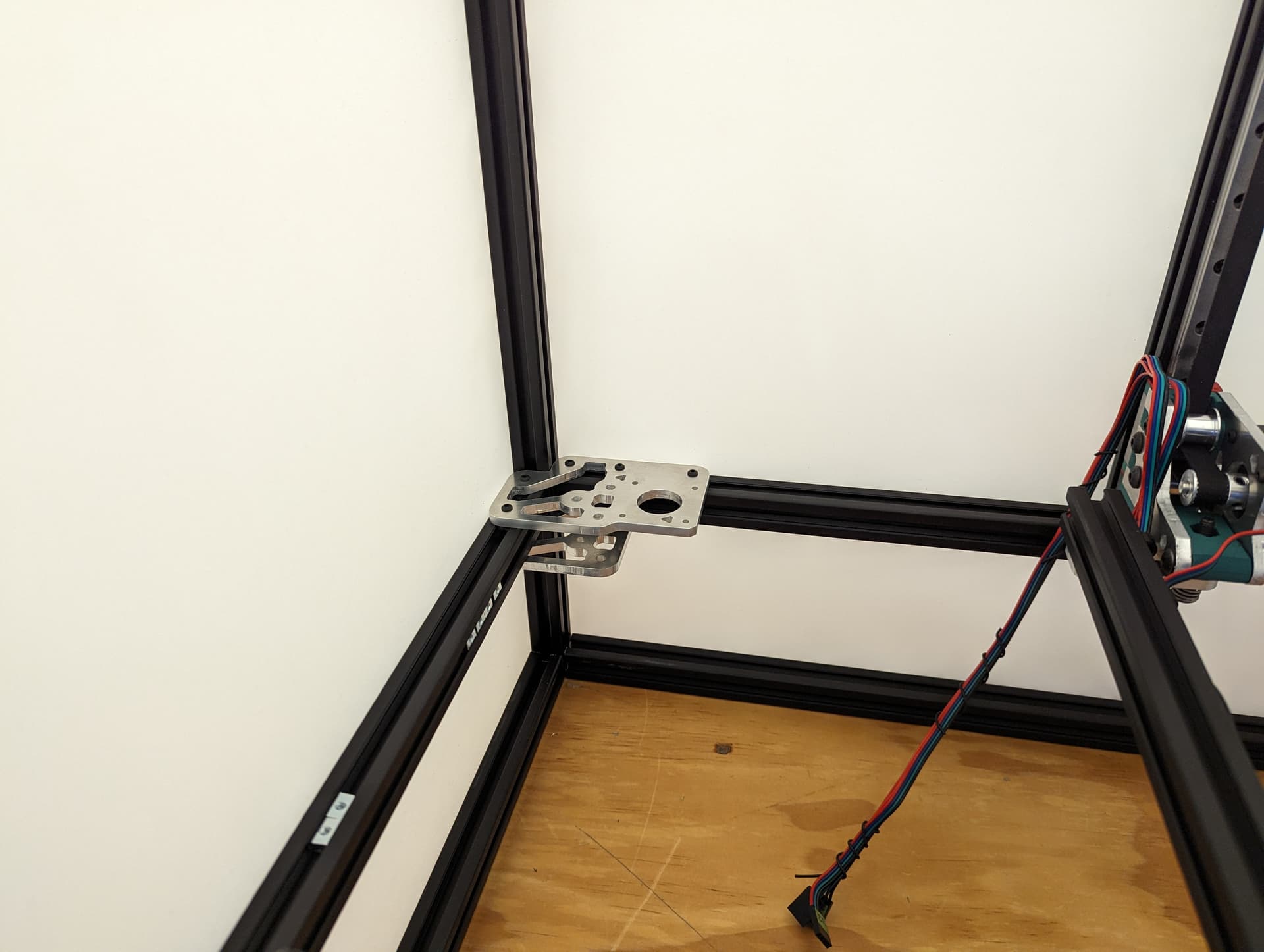
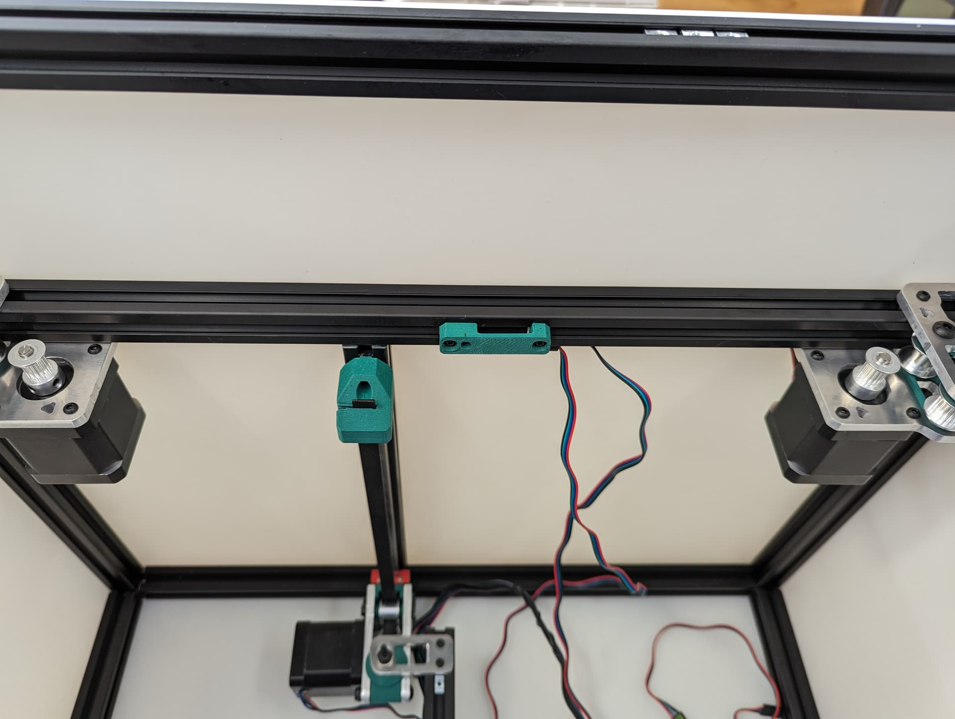
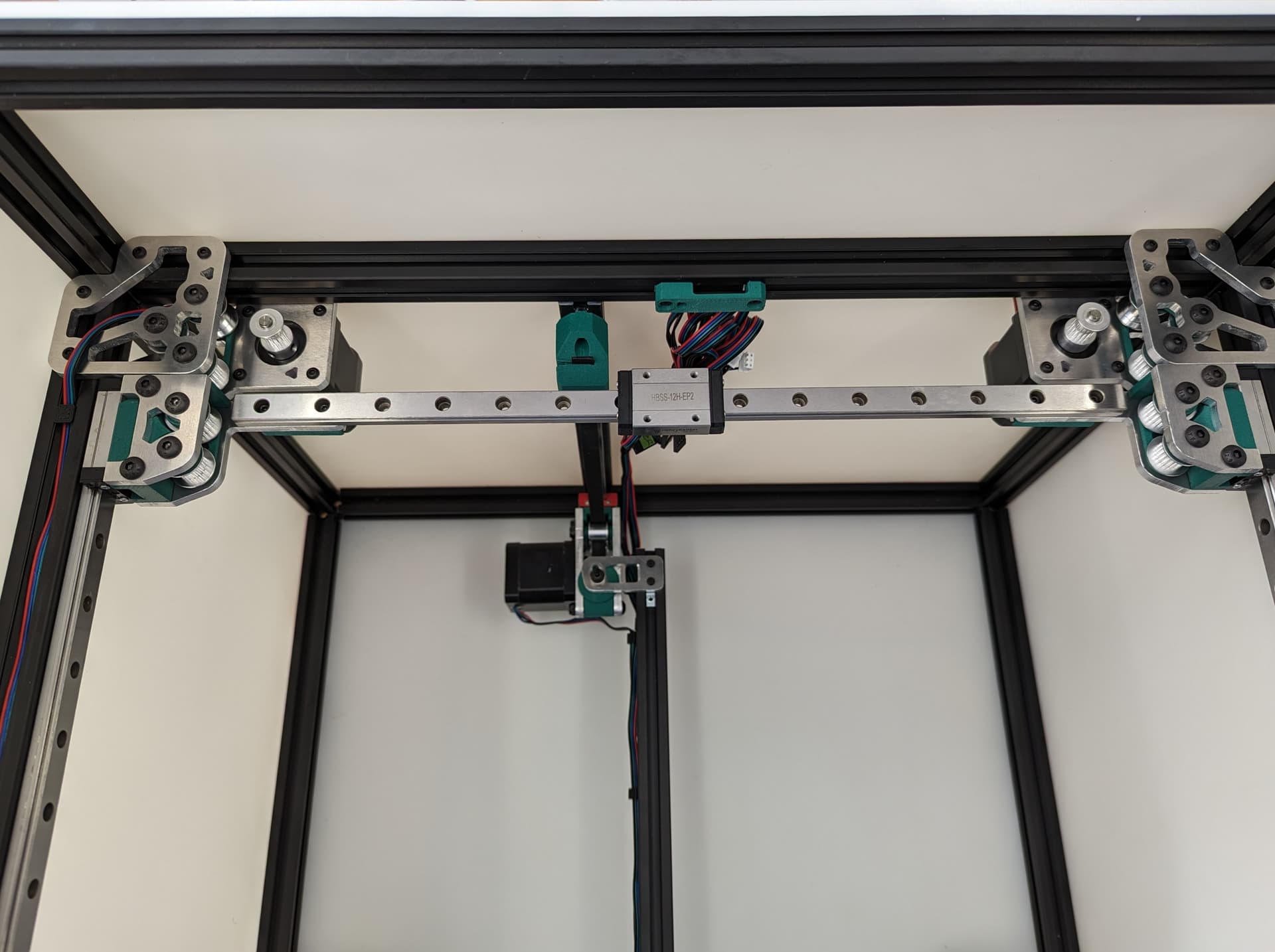
All three Z axes mounted and ready to rock. Notice the bed mounts are different and the way the steppers are facing.
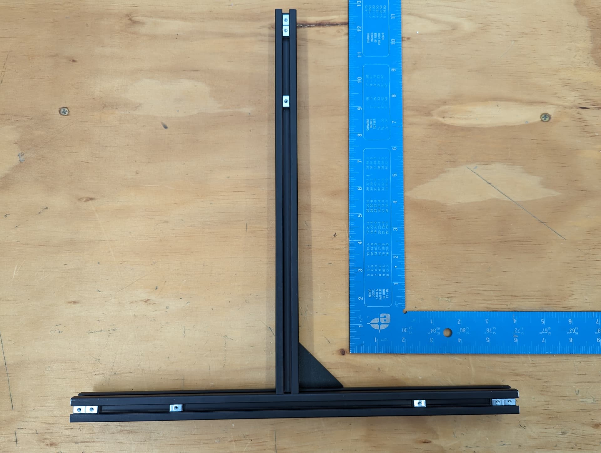
The Bed
The bed frame gets built as square as possible. Take note of the dimensions in the CAD, the rail is not centered.
To make it easy on myself, I made a little mark to where the bed mounts are going to line up, dims taken from CAD.
Load up some Tnuts.
Line up the marks and snug it down.
Showing some wire runs. Steppers on one side power on the other.
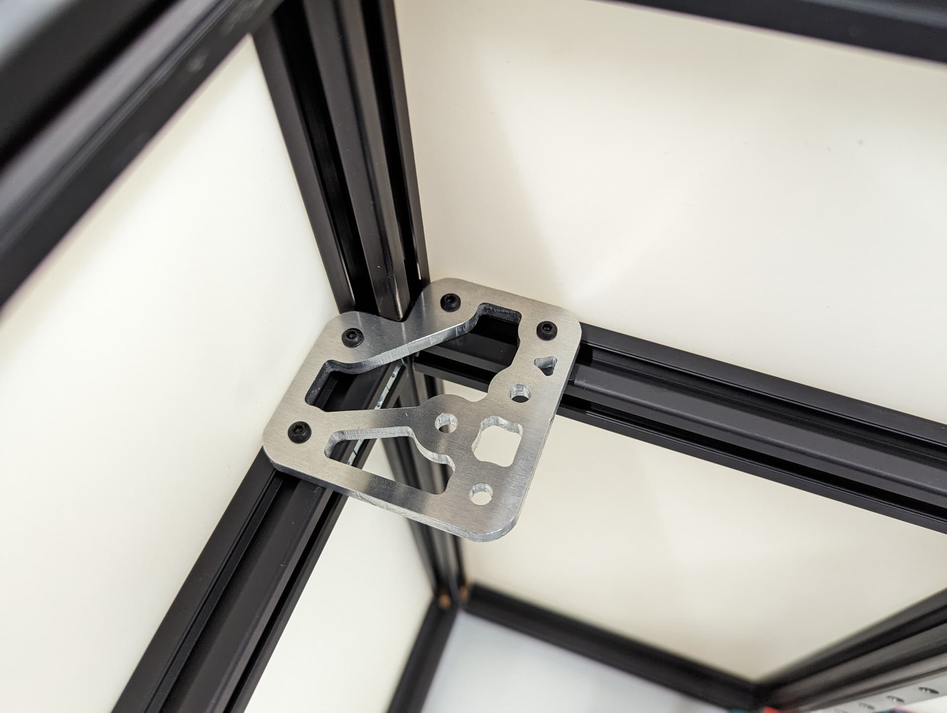
Plated Power Corners
Tops in place, might want to assure your frame is square again, as this locks it in.
Bottoms in place
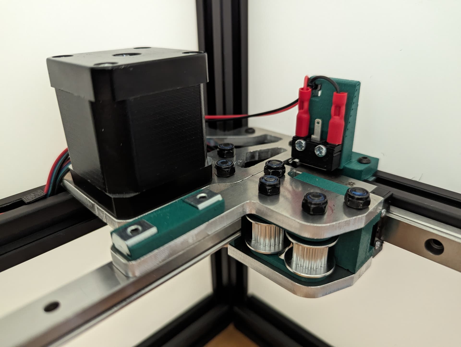
Adding in the spacers and idlers. Toothed idler in the front, the other two are smooth. These need to be very free to move, do not crush them.
If you need to sand down the surface of the spacers, a few light passes should do it.
Add in the stepper, the pulleys get the same paper gap as the rest. If you are super fancy you can color in the top of your stepper to highlight that ultra sexy logo I snuck in.
Both corners done. Wires getting routed towards the electronics area of your choice.
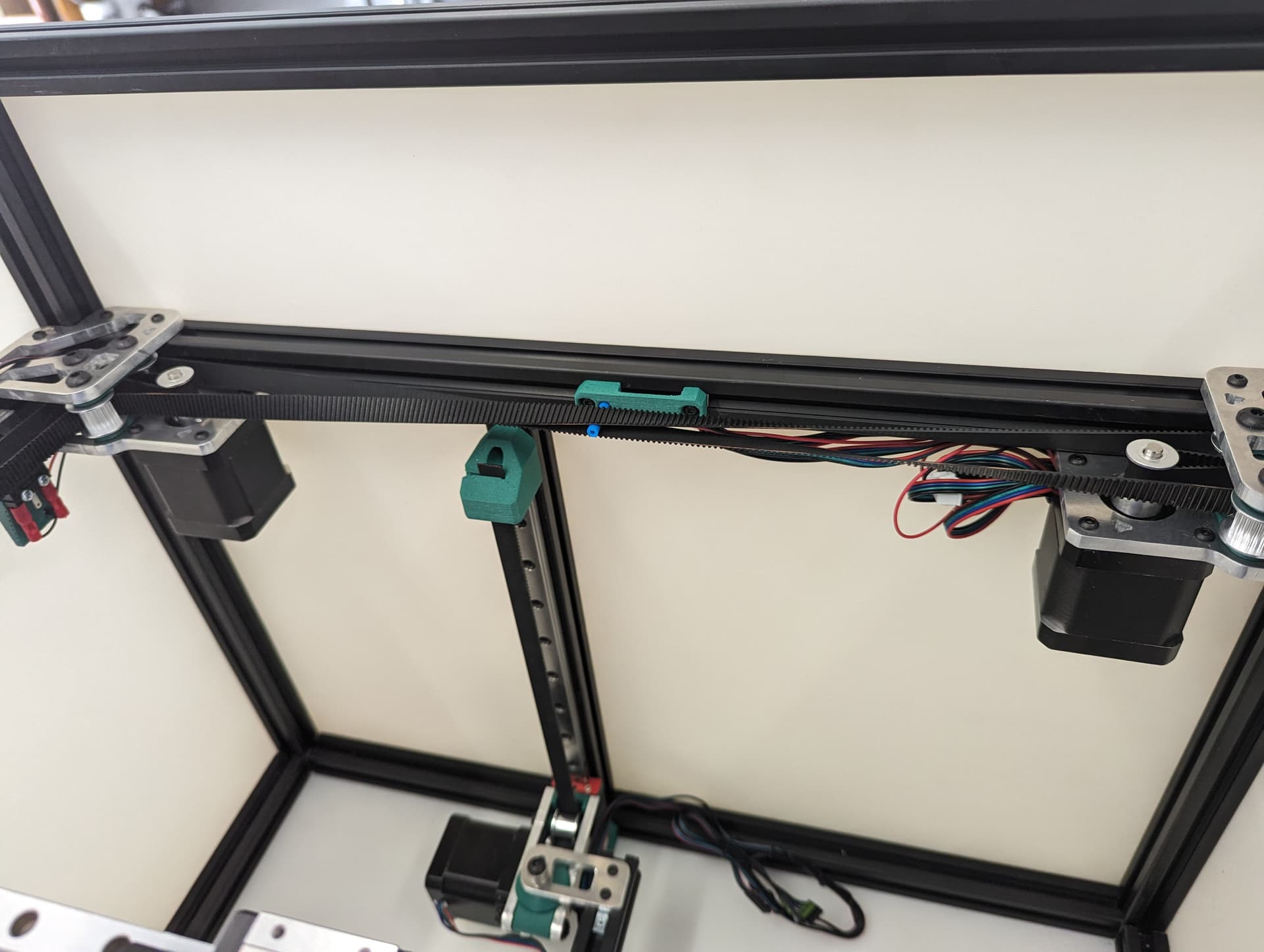
Add in the wire harness and belt separator.
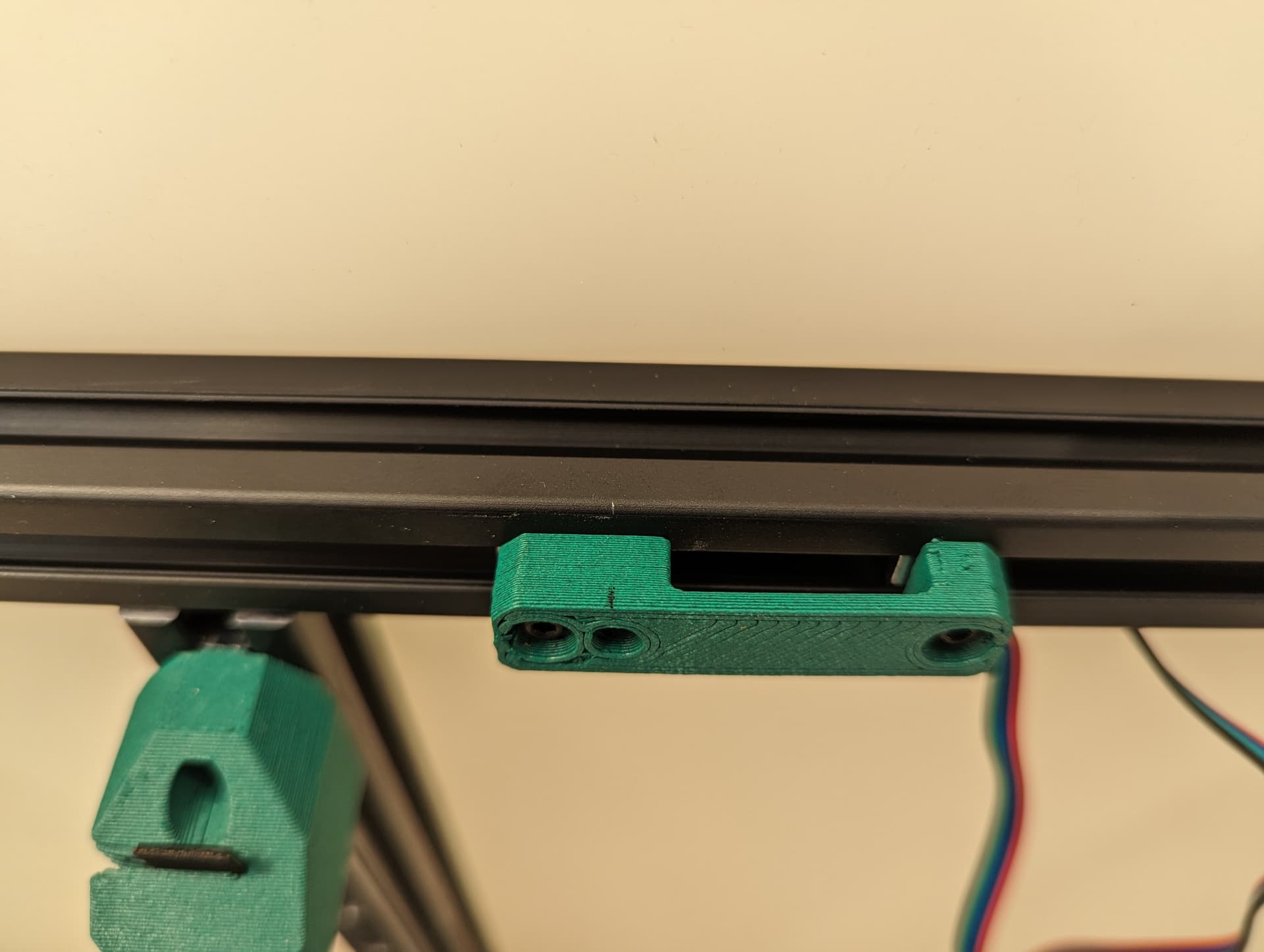
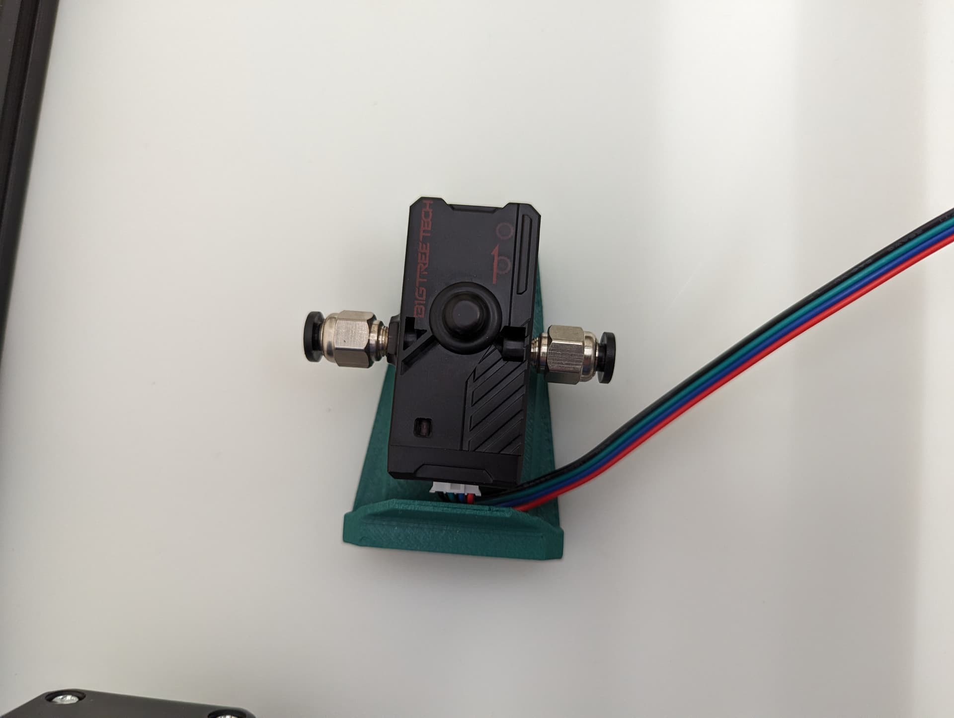
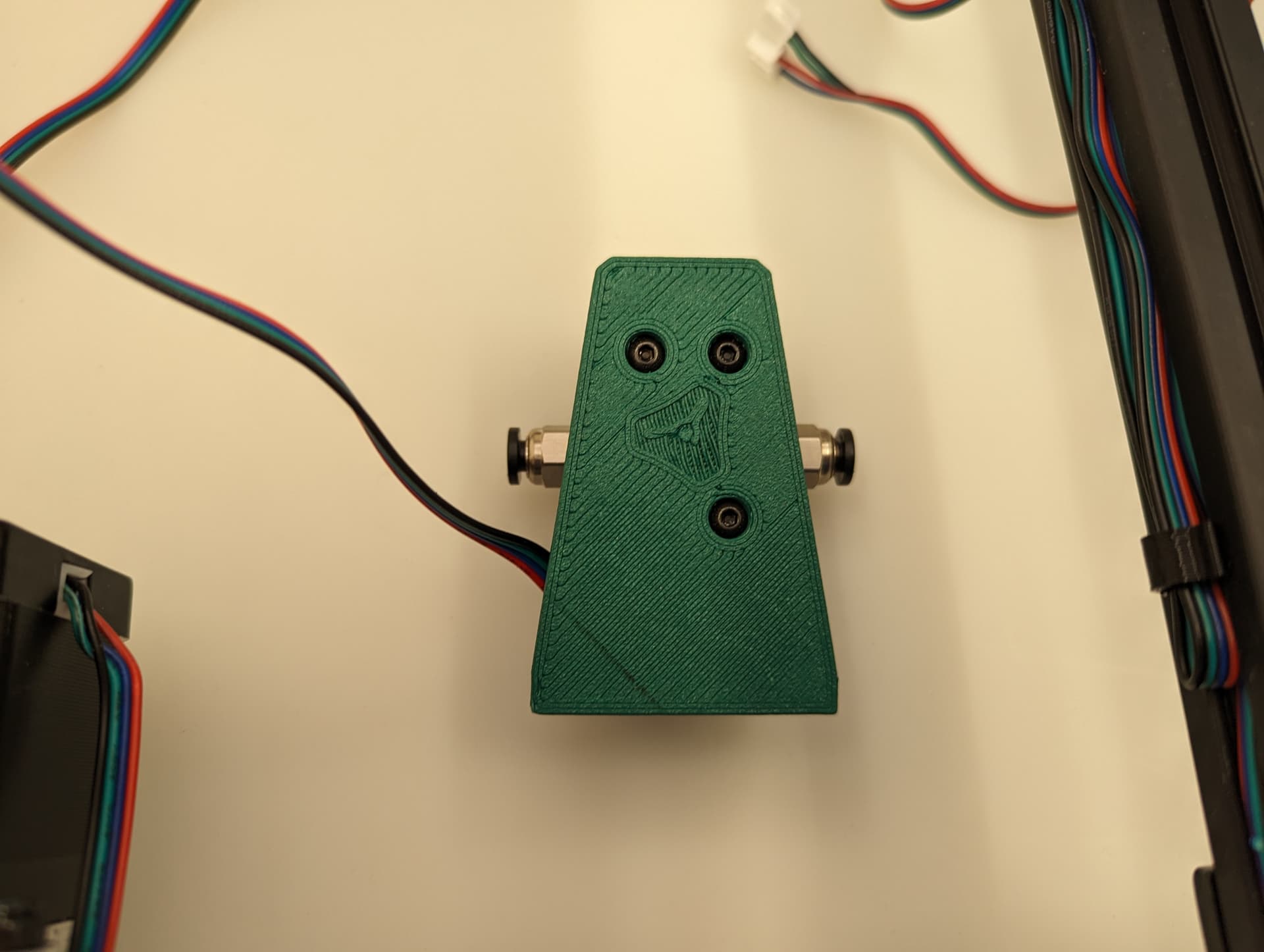
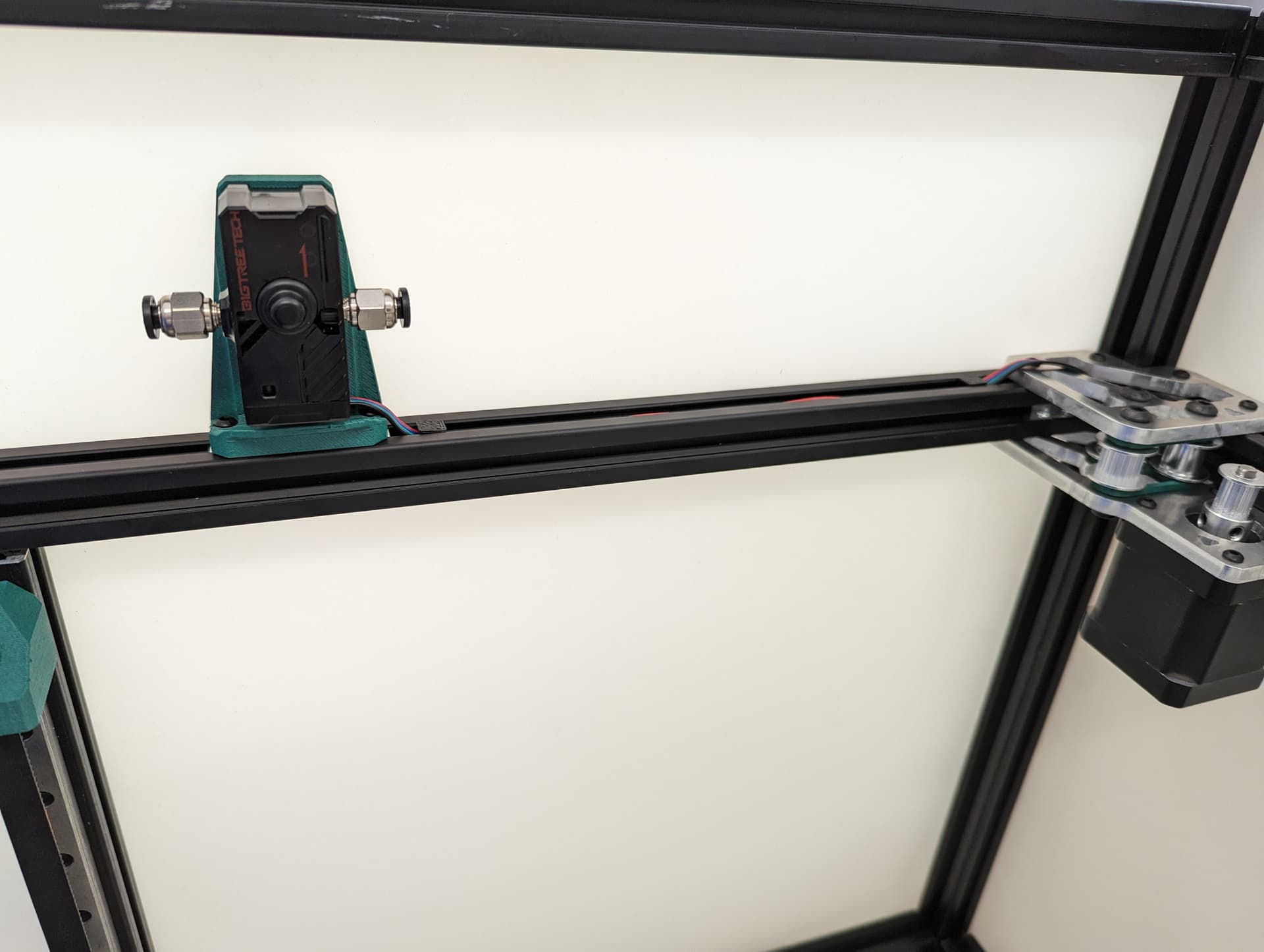
Optional Filament Sensor
The end of the sensor output tube goes in the middle of the travel for your Y axis in relation to the feed tube input of your extruder.
Y Axis
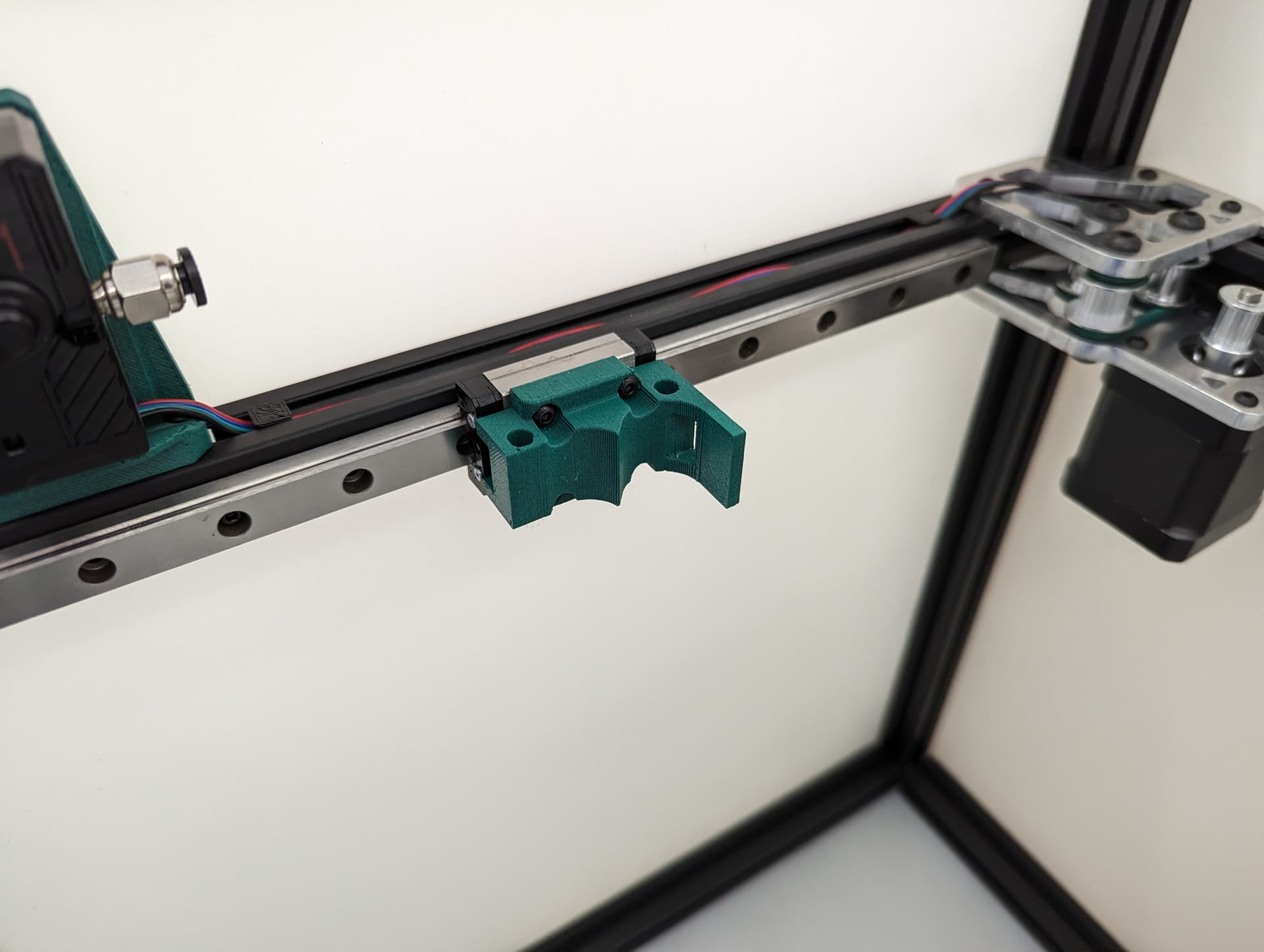
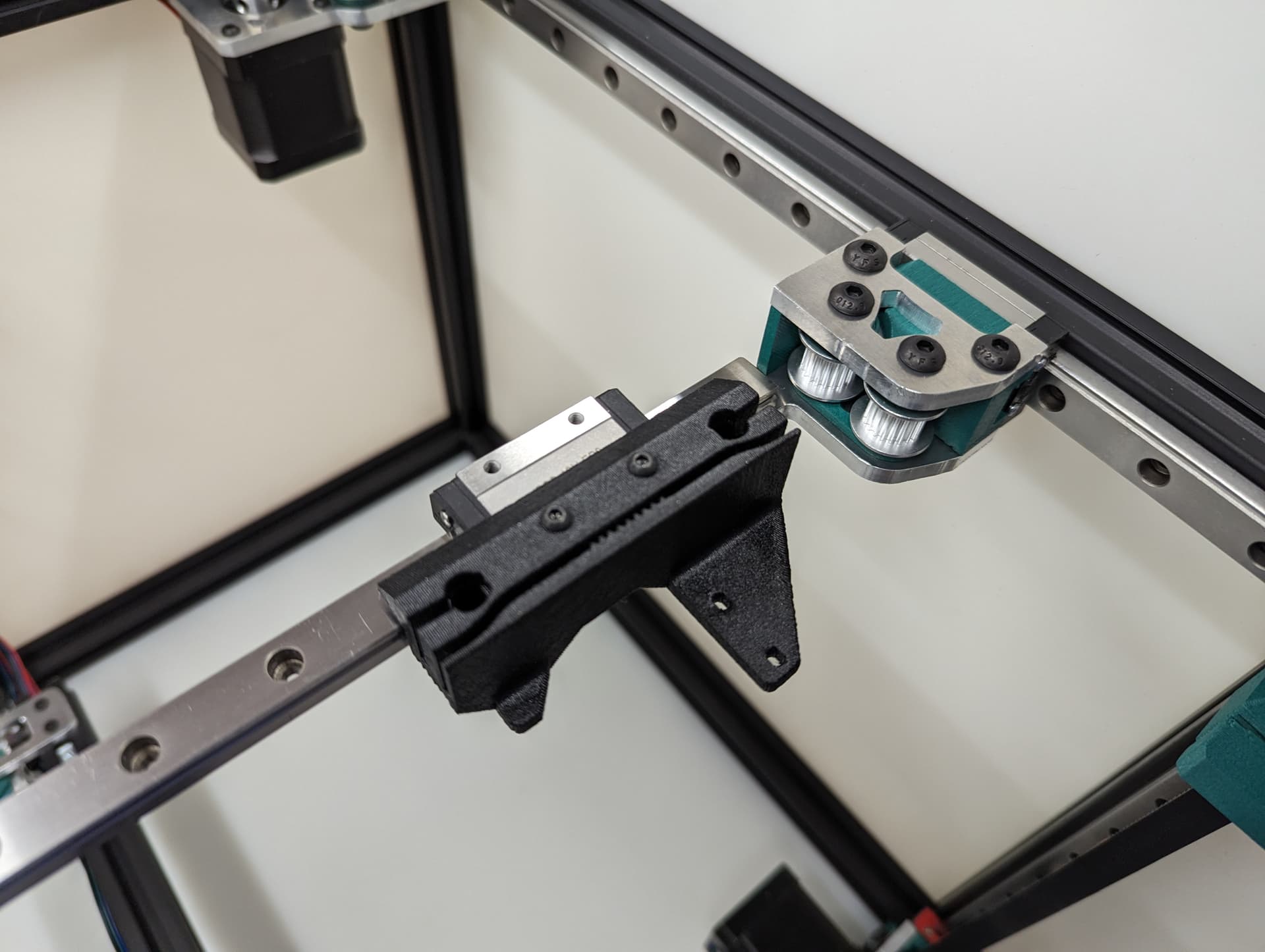
Center the rail on the extrusion, The end is flush with the corners. M3x8mm screws to secure.
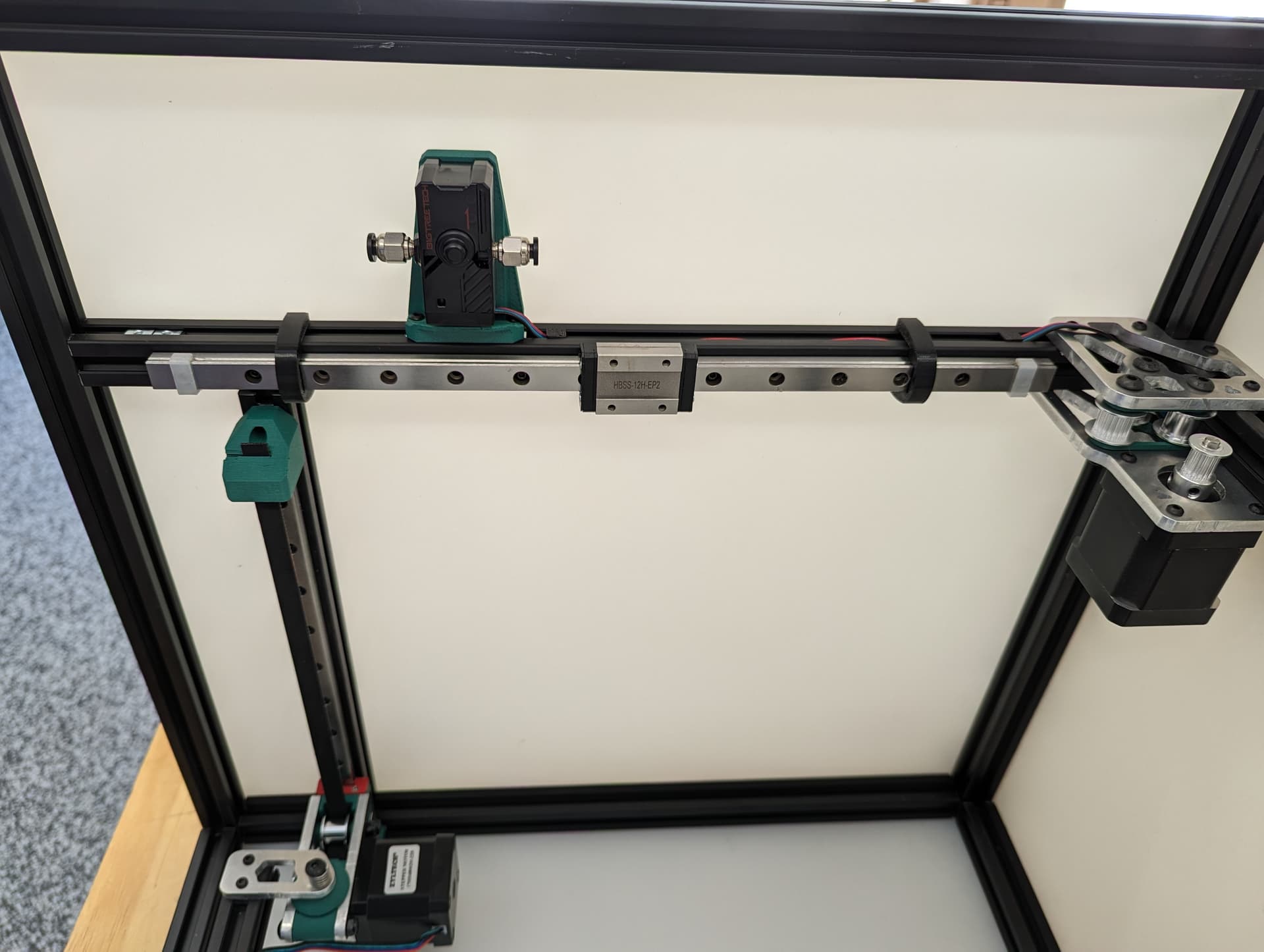
Snug down the truck
Add and snug the plates.
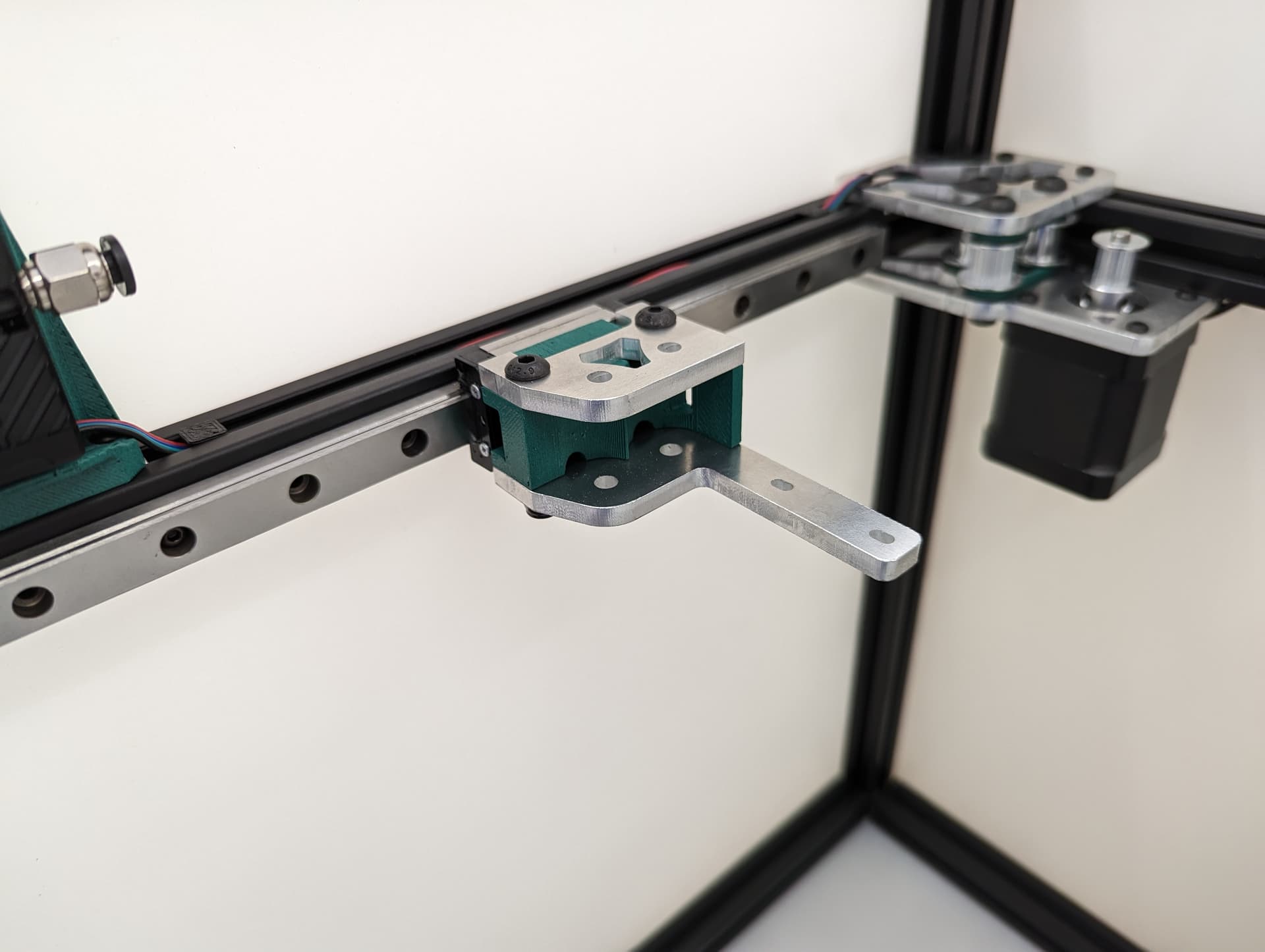
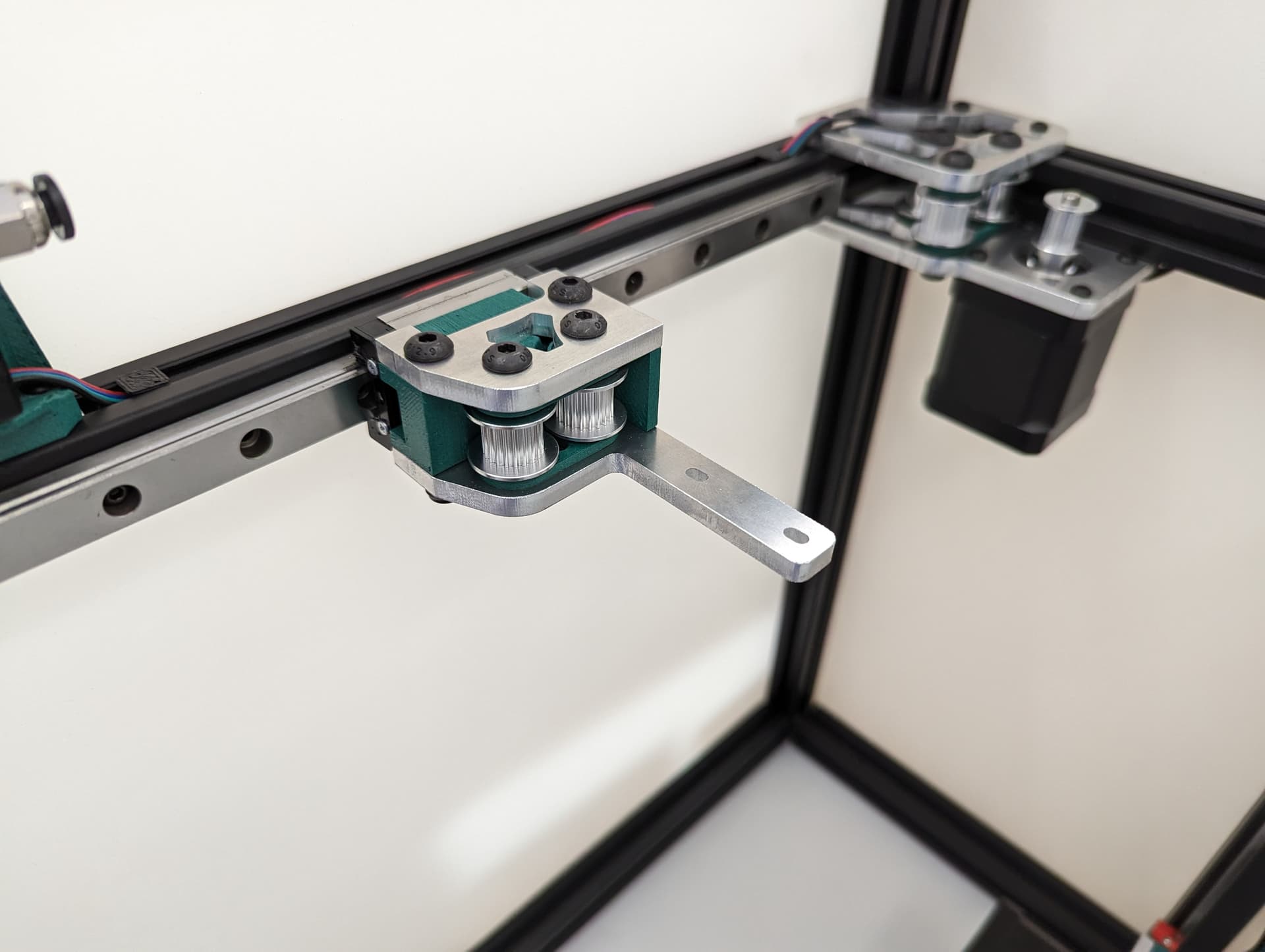
Add the idlers and spacers, again, be sure to leave free play, sand the spacers if you need.
X Axis
Showing some t-nuts in the optional X axis locks, you can use washers and locknuts if you prefer.
-
Add the rail, make sure it is centered left to right, and that it is centered front to back on the lower rail plate. In this step when you snug up this rail you will want to make sure both corners hit the trucks the same and there is no gap on either side. This will mean your axis is starting nice and square (you can move it with the belt tension but more on that later).
-
Move the rail front to back make sure it is smooth. This is the best place to make robot noises while testing, if you have kids make them help.
-
Make sure the front upper frame corners do not move in and out, measure them when it is all the way to the front and the back. If they move in and out, there is a big issue with the frame, fix it now.
Belt Tensioners
Add the tensioner screw and nut. Be sure the nut is seated, or later on it will bum you out when you try to play this thing like a guitar. this the screw that sets the belt tension.
Add the top and bottom brackets. You will loosen and tighten these four screws when adjusting the belt tension, these lock the tension you set.
Spacer and idler…is that idler able to move freely??
Ready for belts.
Initial position is touching the rail.
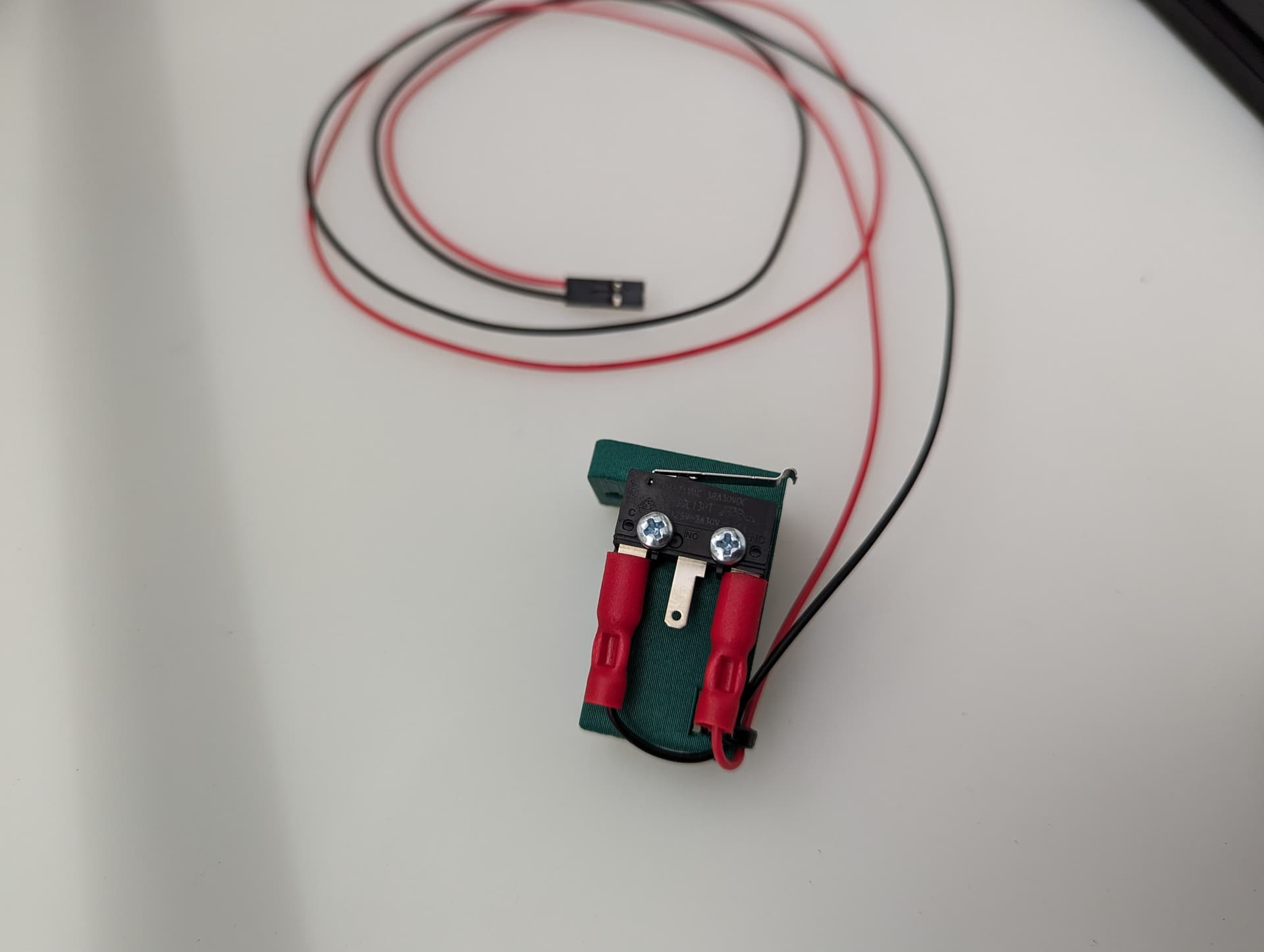
Y endstop
Wired, Normally Closed for easy diagnosing of crimp issues, and highest safety. Mounted to the bracket with M2.5mm screws.
M3x10mm screws mount this to the frame.
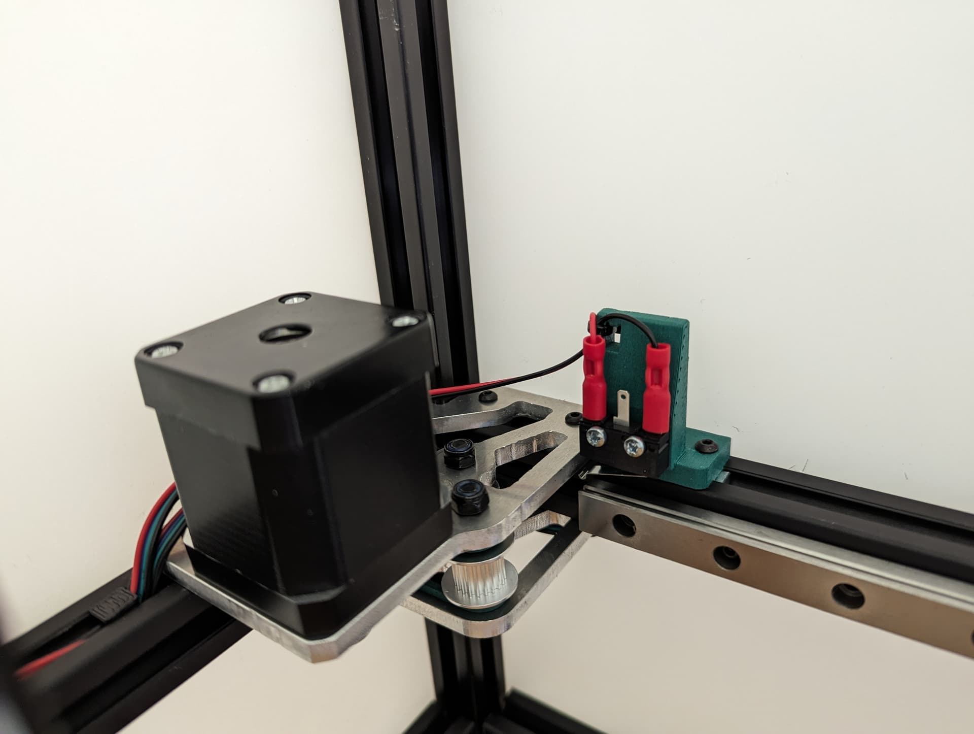
Set the trigger point to as close to the corner as you can without getting any snags. You can move and hear it trigger. The further into the corner you get it, the more Y axis room you have to work with later.
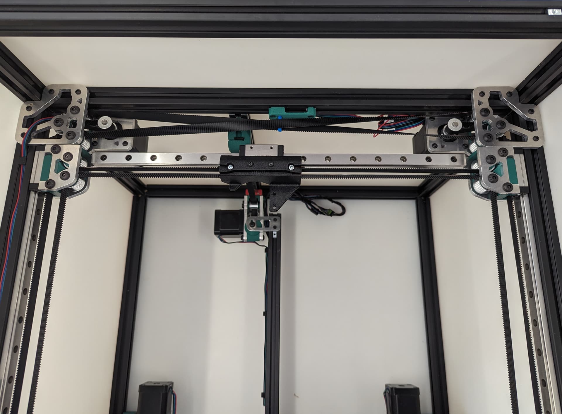
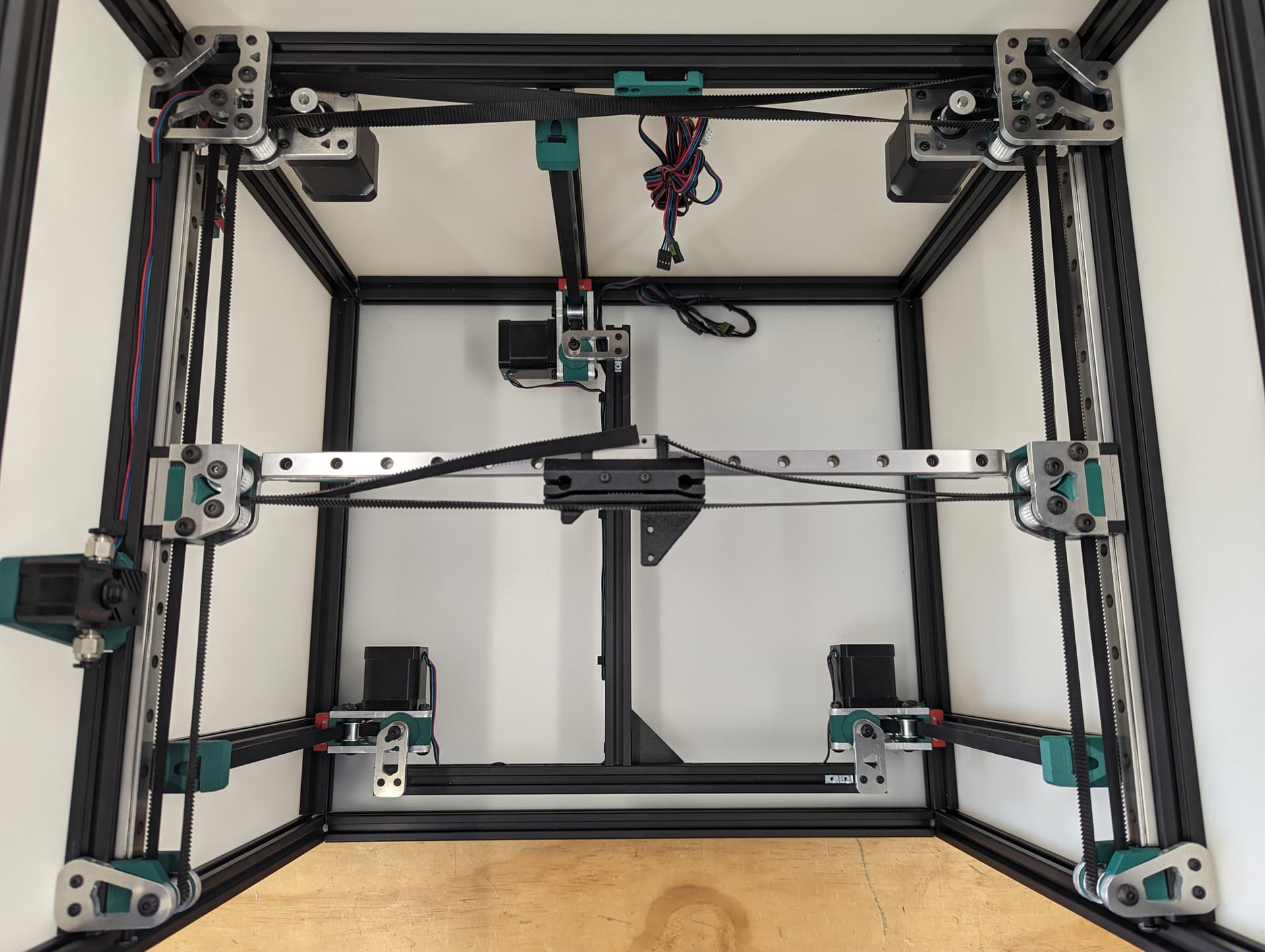
XY Belts
Add your lower core piece and snug it in place.
Take your time. Follow the numbers. Make sure your twists are the same direction. The belts should look like they are doing the same thing in each half twist.
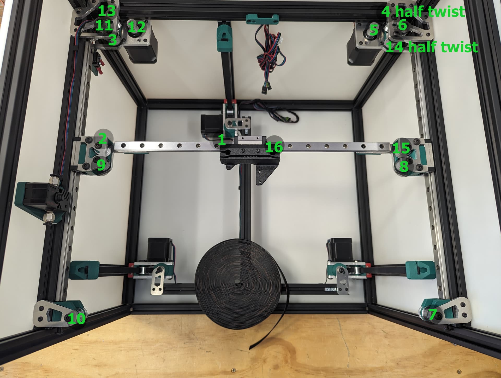
Skip the middle lock for now.
Look at the twists.
Lock the belt ends in place with a M3x10 fastener.
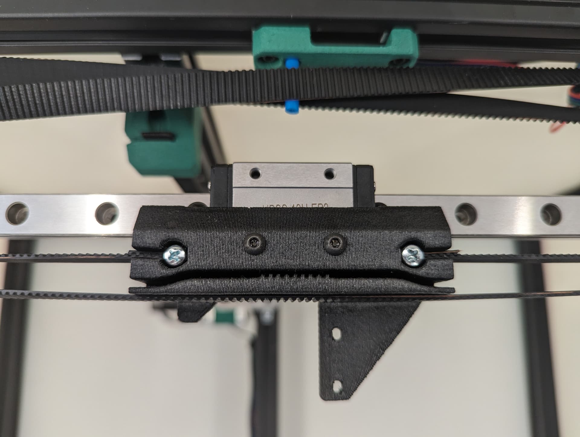
Lock in the tension equalizer section. Make sure the corners are still touch the trucks the same on both sides to know you are starting off with fairly equal belt tension.