Middle
Step by step, lots of pics, few words. Click on the pictures to enlarge them.
“Snugged up” for 5/16″ bolts or M8 ≈ 5.5 NM
XYZ
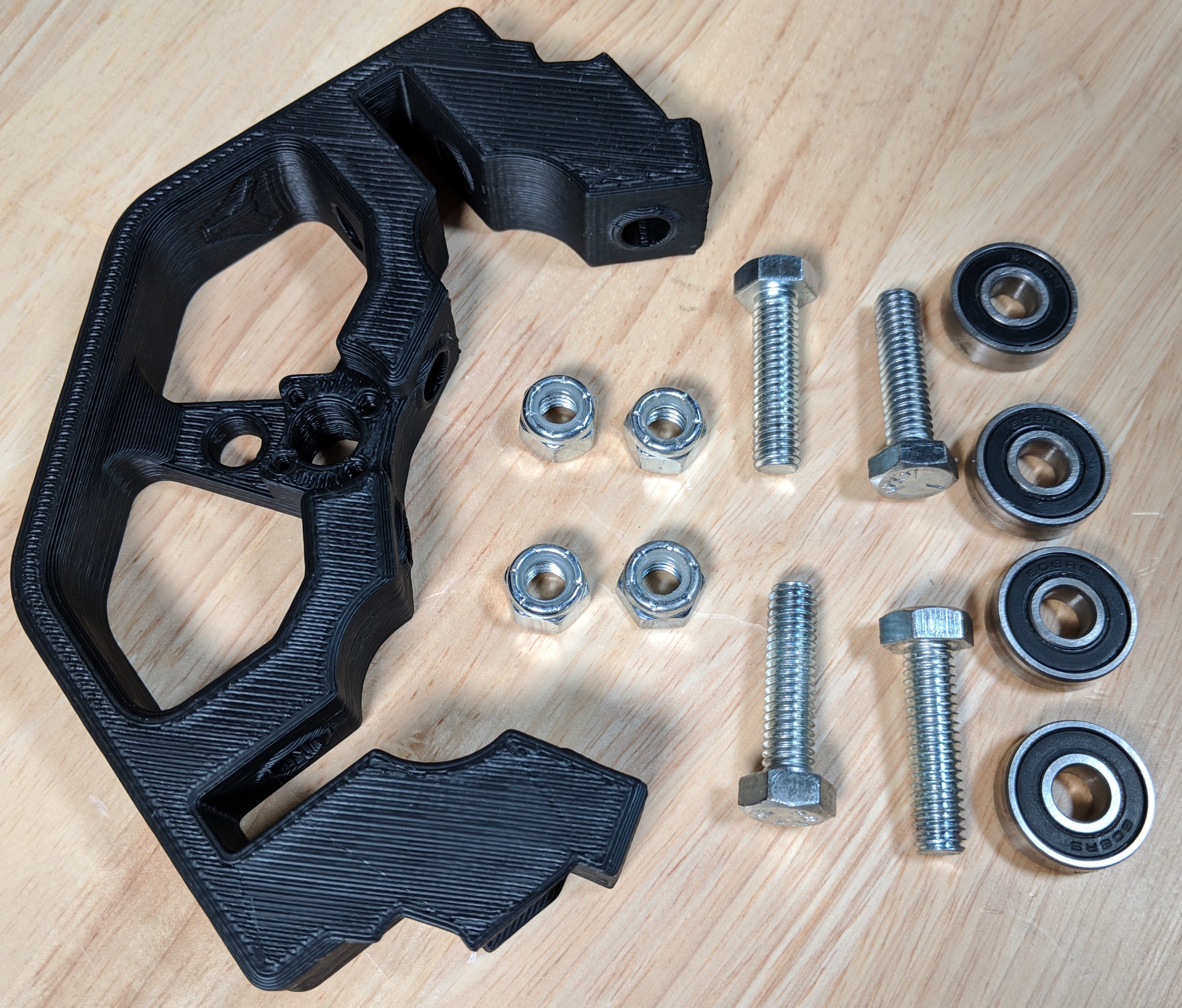
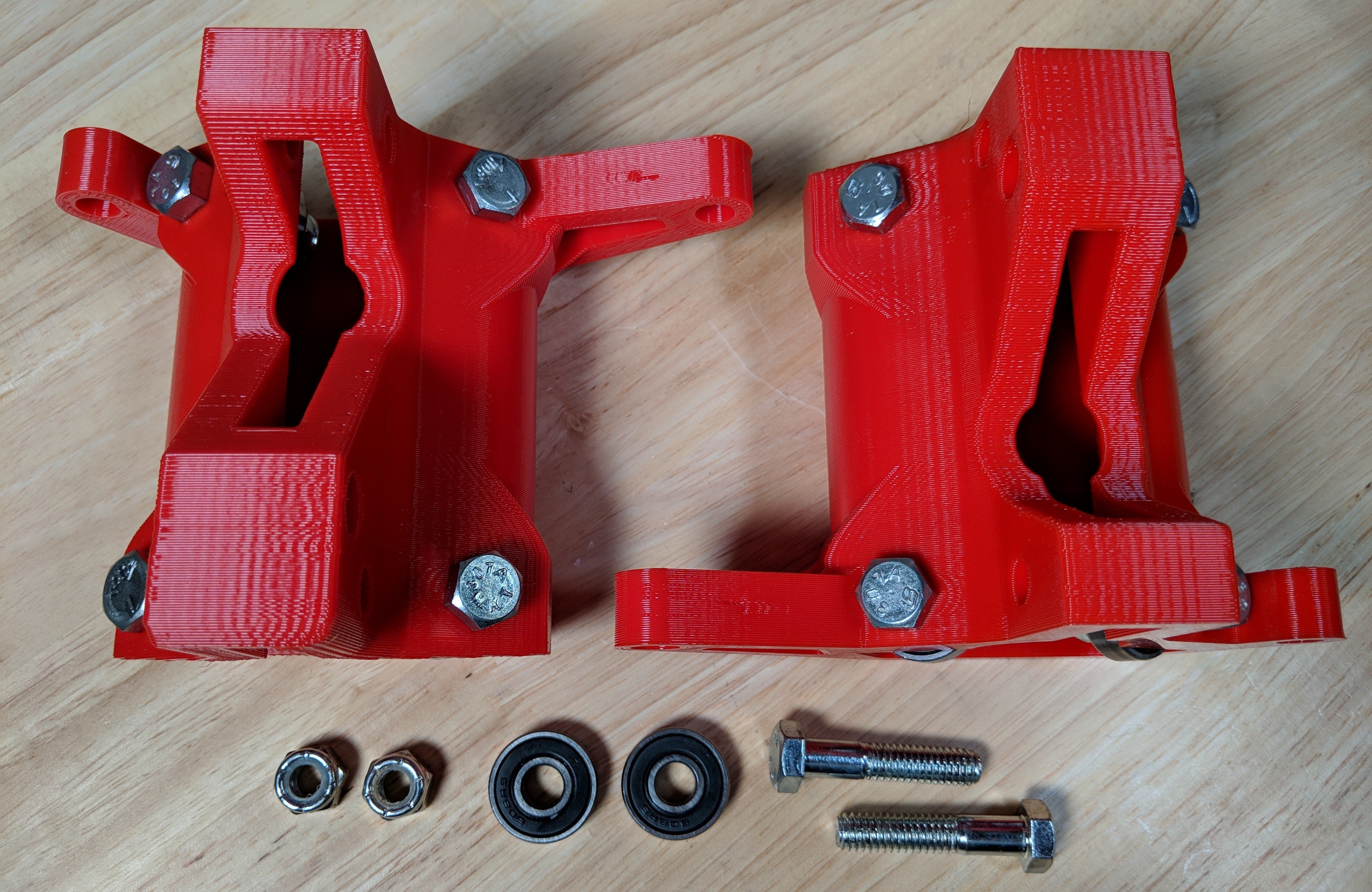
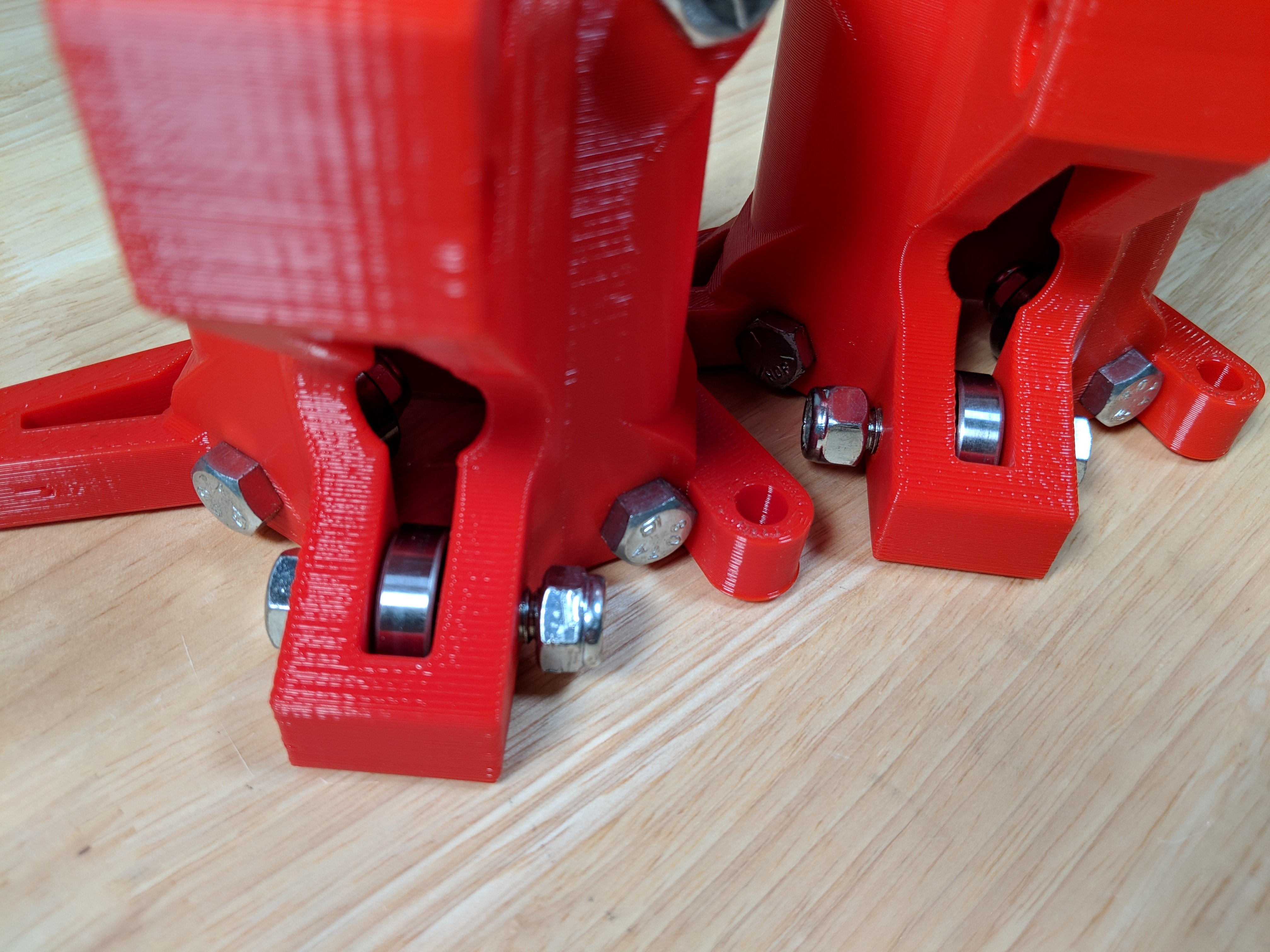
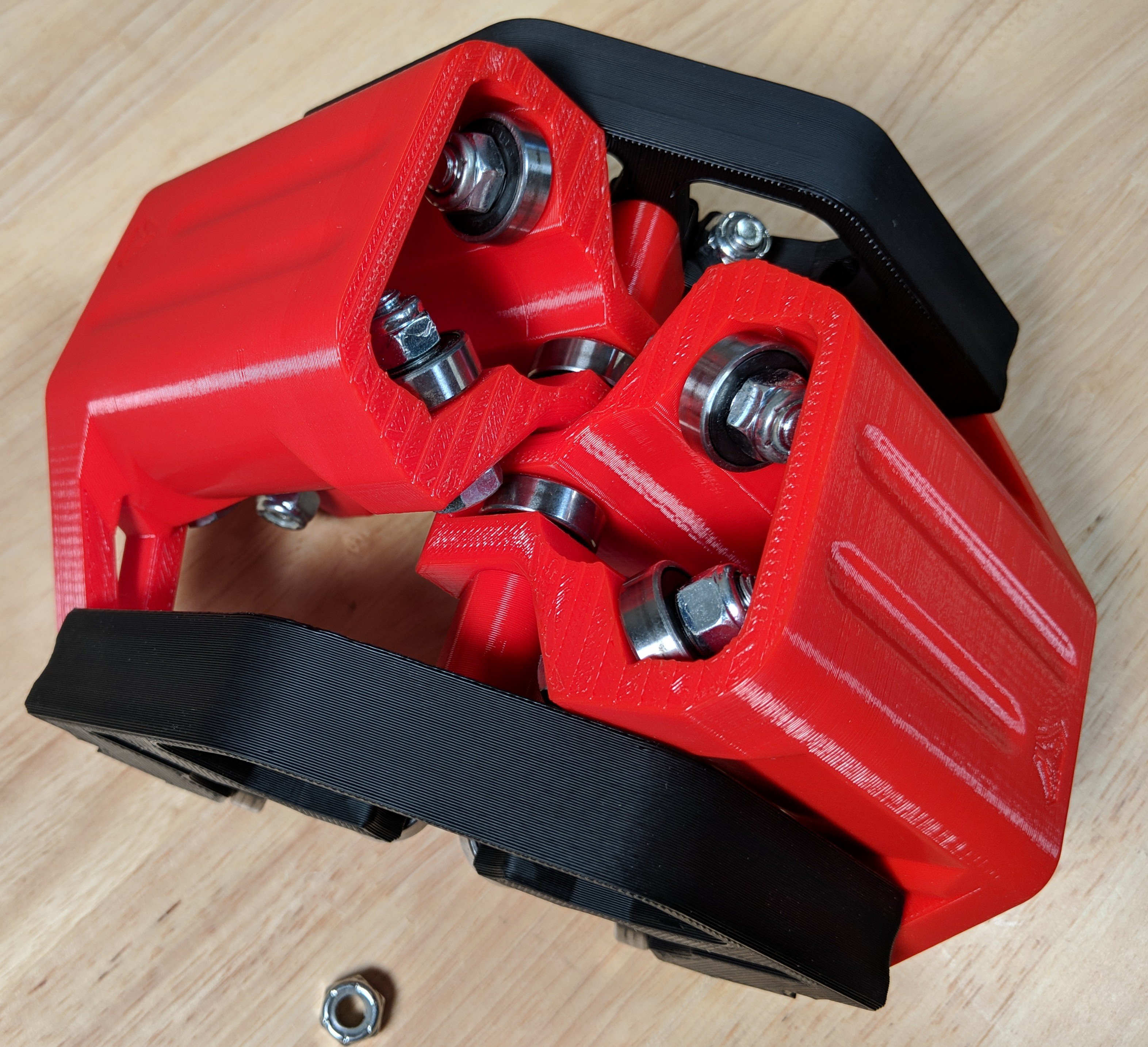
- For each XYZ part, using 4x 1.25″ (M8 x 30) bolts, lock nuts and 608 bearings assemble as shown:
-
Make sure the bolt heads face as shown for Z-Axis clearance.
-
These bolts can get snugged up and should not be touched again.
-
YES, the outer nuts are a pain to tighten if you are using 5/16″ hardware (but easy for 8mm). Pre-thread the nylocks to loosen them up a bit then just wedge a small flathead screwdriver in there and tighten it. No big deal. This is not going to change, we have metric and imperial hardware to account for. I do not want to maintain two sets of every part for something that gets done one time.
XY
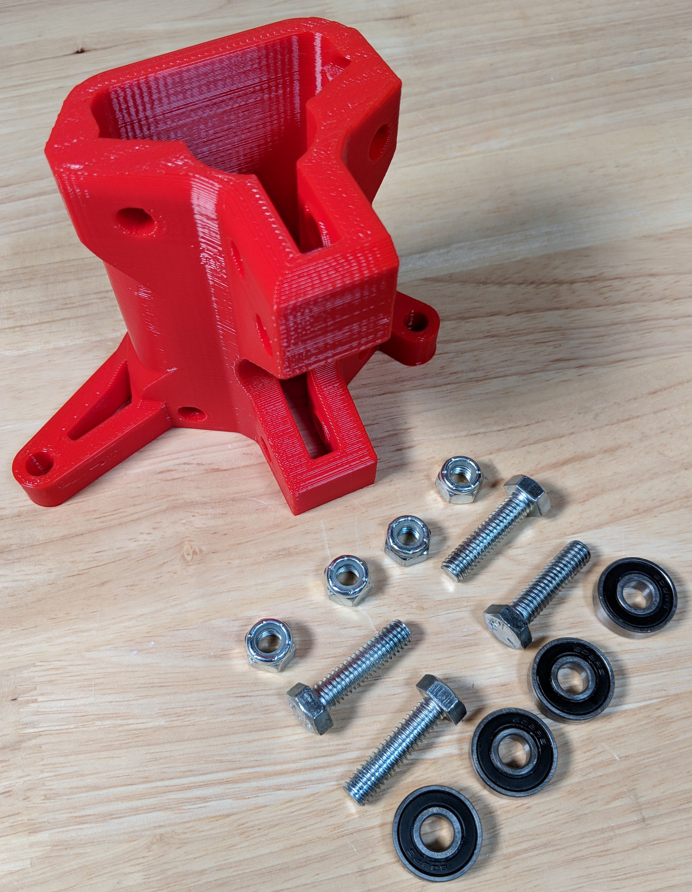
- XY part, 4 1.25″ bolts (M8 x 30), nuts, and bearings.
-
Assemble these as shown with the heads out.
-
Do it for both XY parts.
-
These bolts can get snugged up and should not be touched again.
These bolts can get snugged up and should not be touched again.
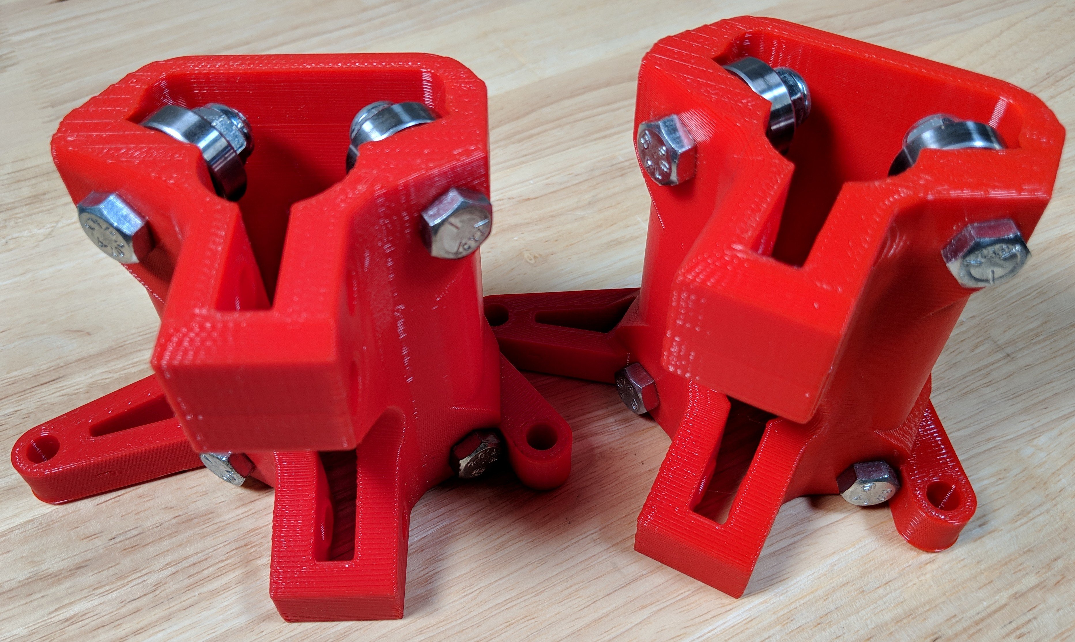
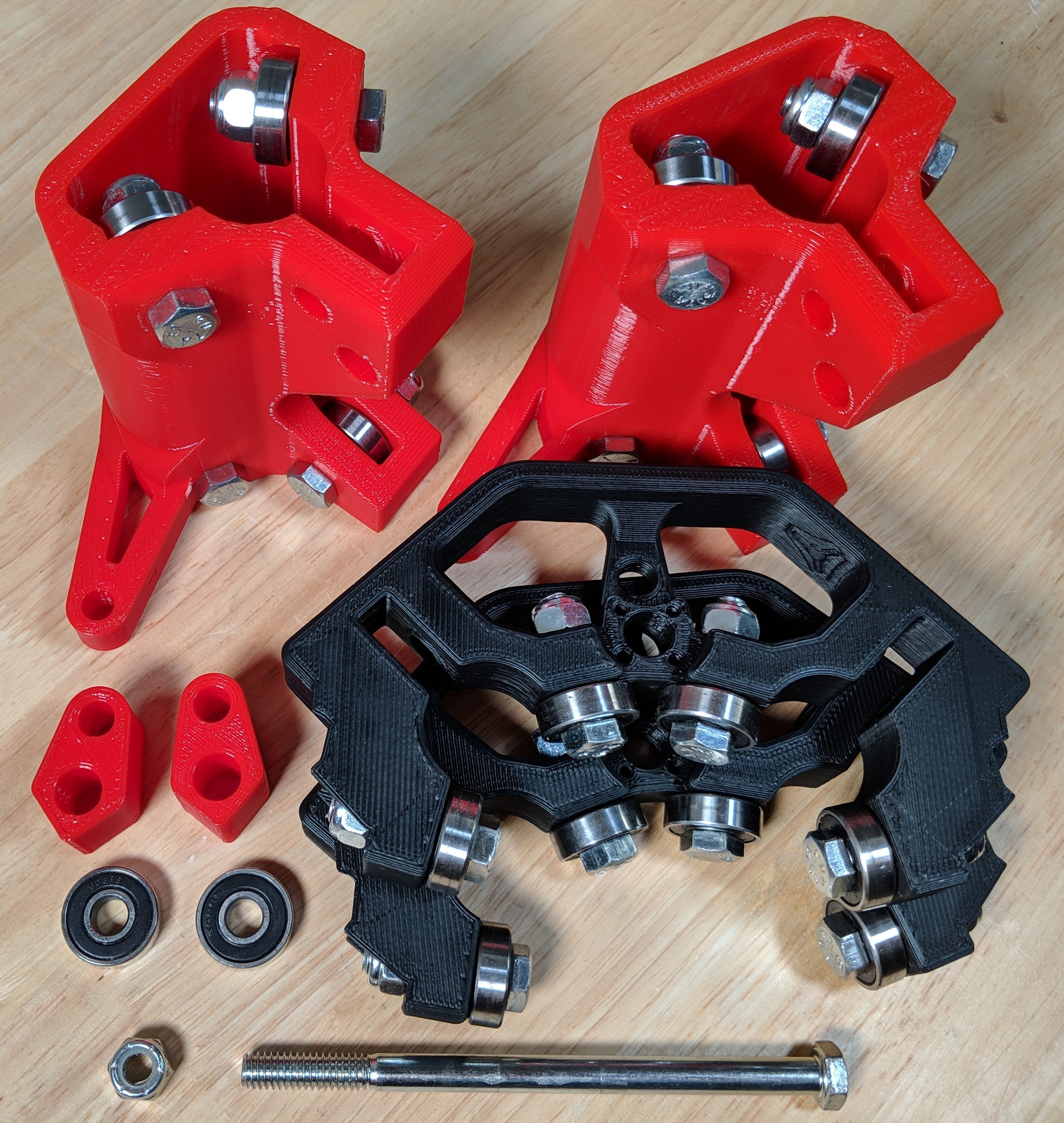
Using the 1.5″ (M8 x x40) bolts, nuts and bearings assemble these into the end of the XY parts that only have 1 hole.
- As shown on the picture on the right the heads should be put in in opposite directions (purely cosmetic), when assembling later these heads should face up.
- Tension Bolts A – Control X and Y Rail tension, slight effect on the squareness. More on this at the end.
- These should be left extremely loose, just tight enough to engage the nylock on the lock nuts.
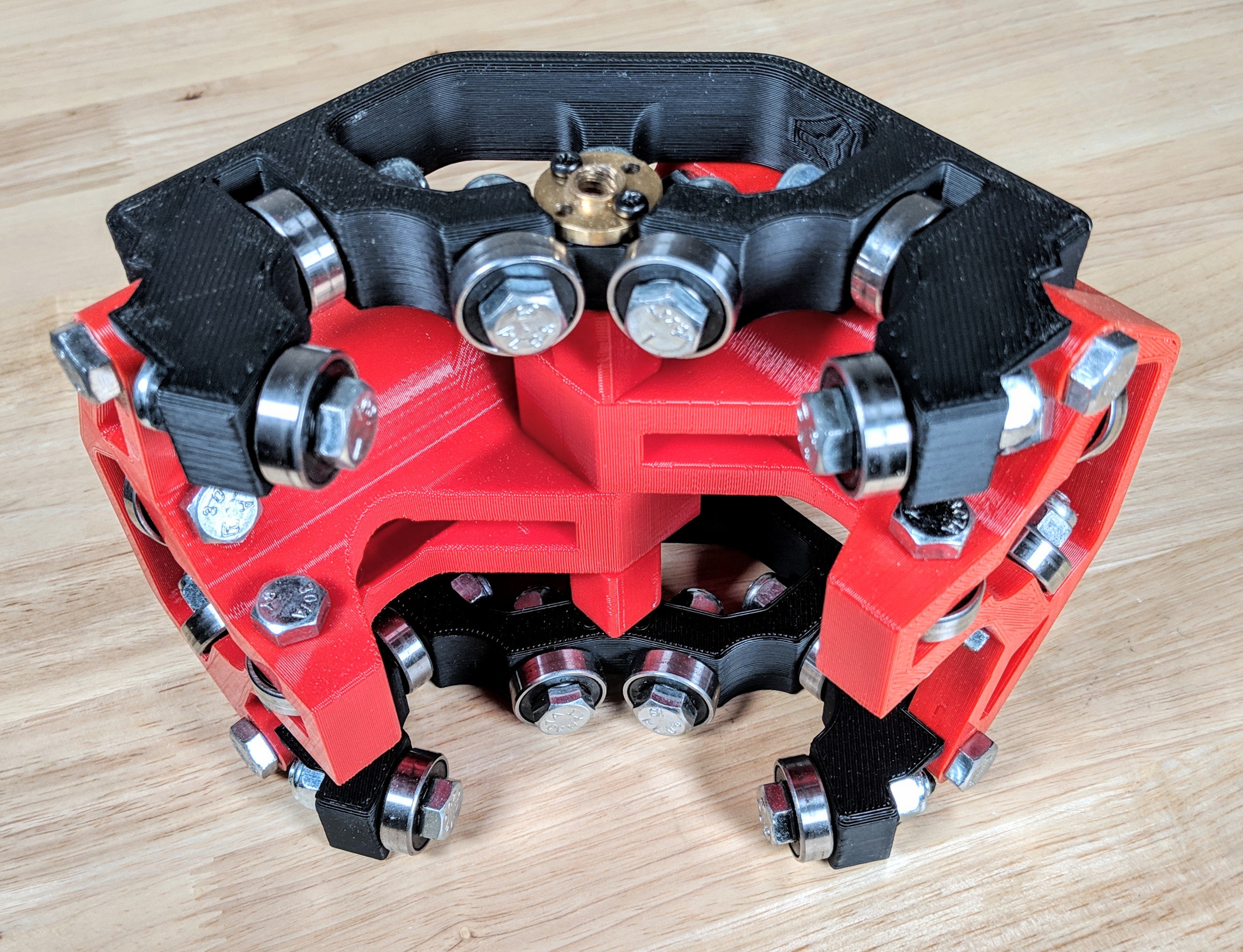
Tension Bolt “B”
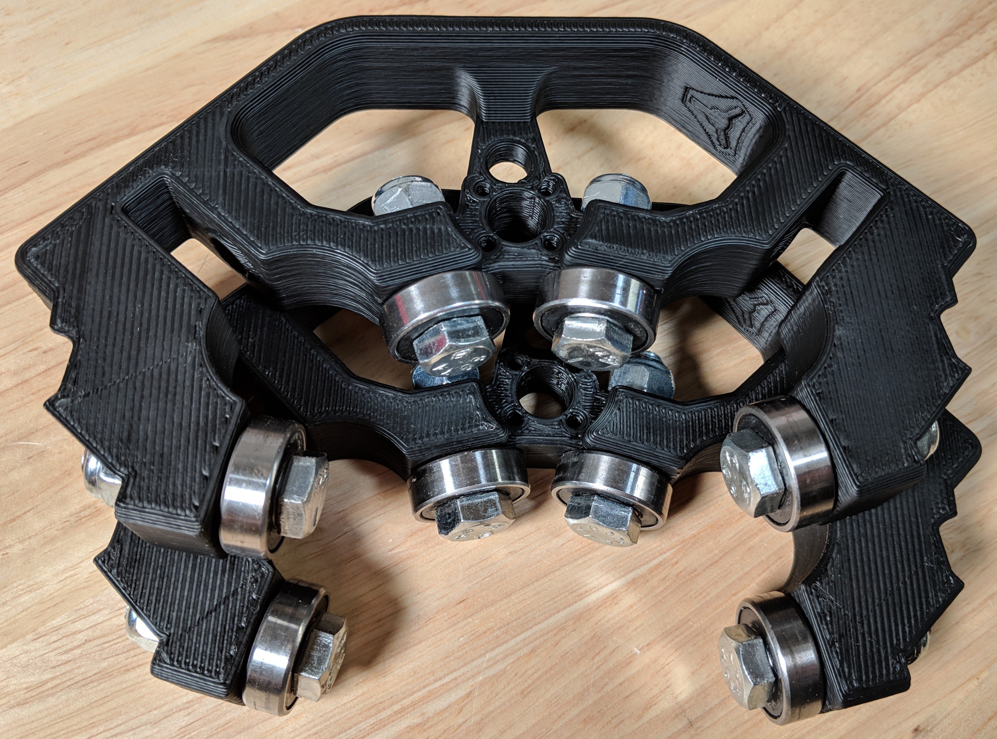
This step uses the XY, XYZ, Lock Nut, 5″ (M8 x 130) bolt, 2 bearing, both gantry spacers, and a nut.
The 5″ (M8 X 130) bolt goes through the XYZ plate.

Next is a gantry spacer.
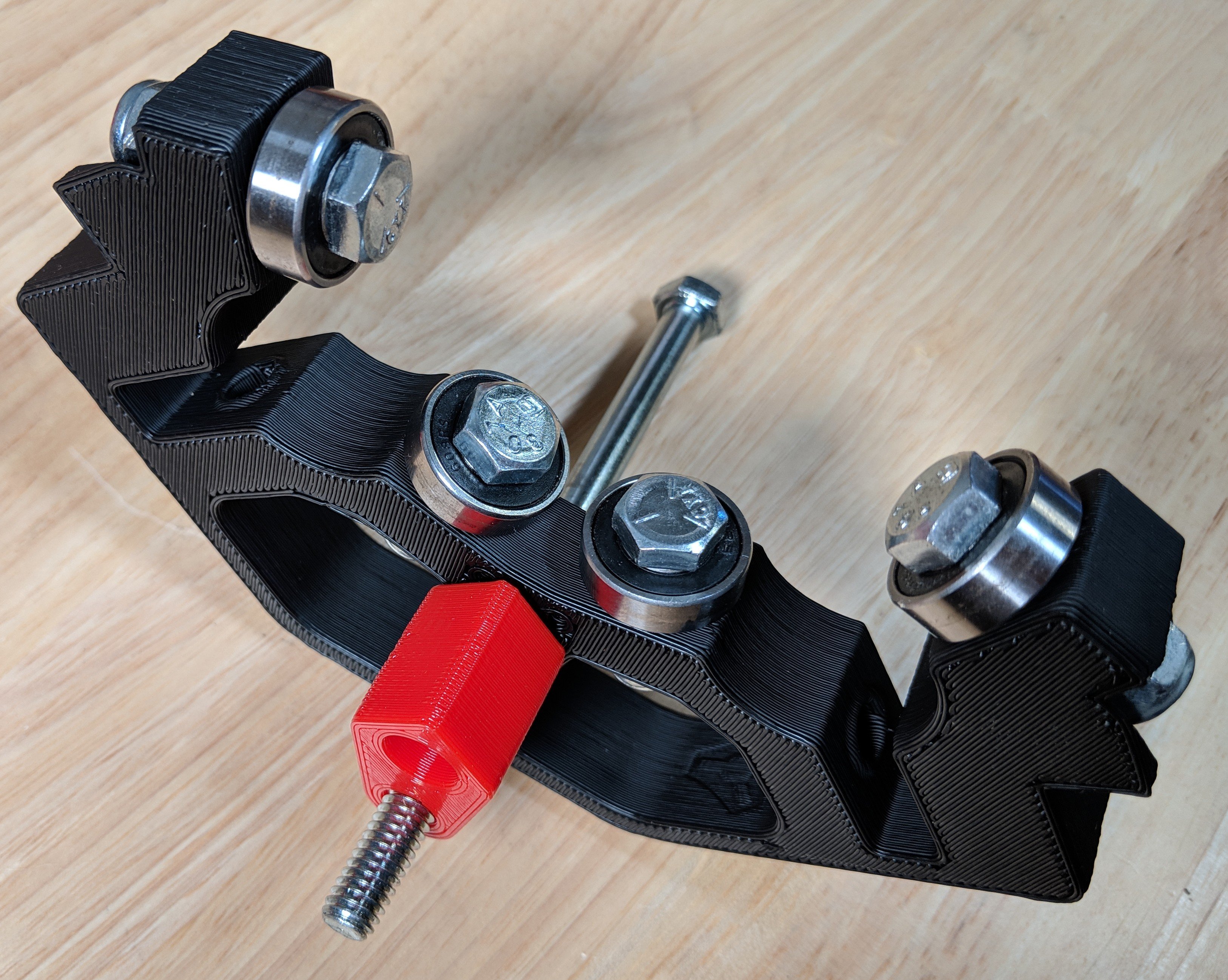
Add the XY piece, align it with the hole on the side of the XYZ piece.

Insert a bearing into the XY piece.
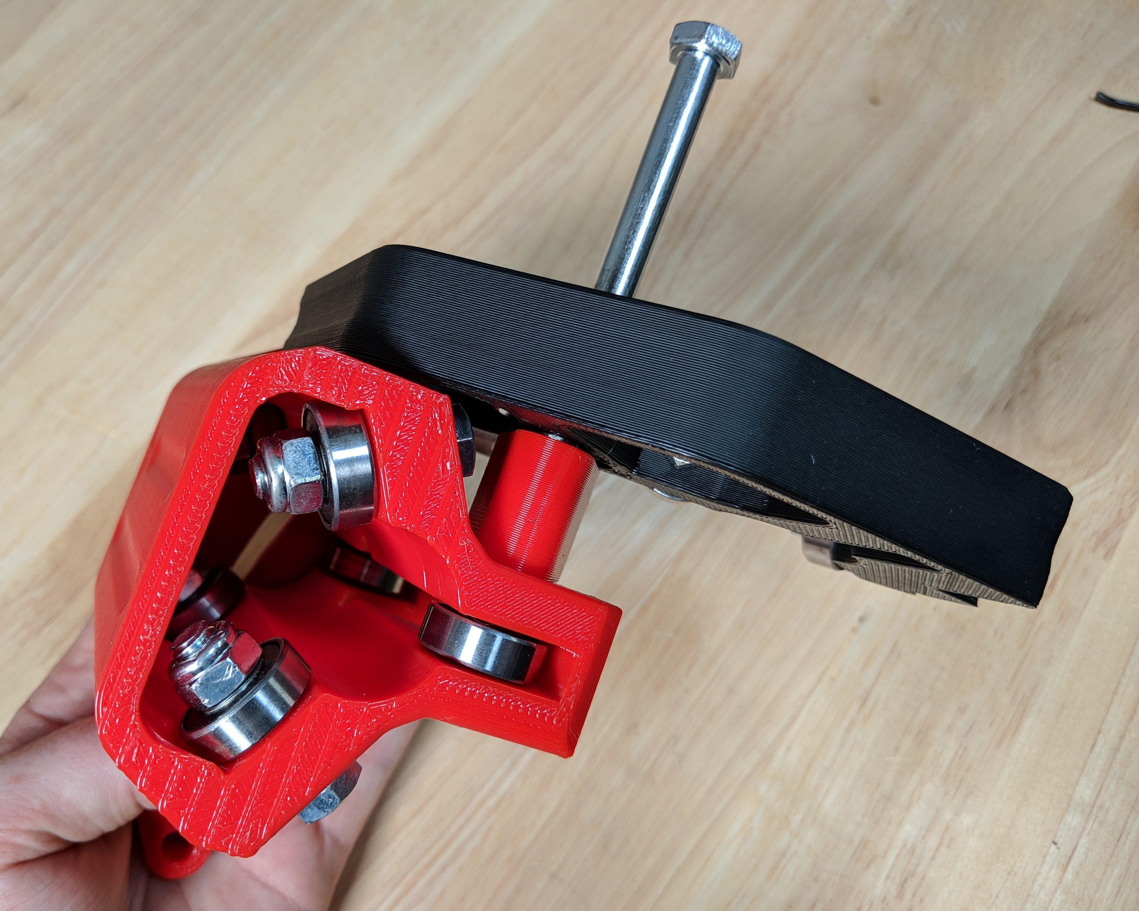
The second XY piece is added to the stack, again lining up the side hole.
The second bearing is then added.
Add the second Gantry spacer.
The second XYZ piece is next, upside down as compared to the first. Like face to like face.
Followed by the lock nut.
The lock nut should be kept loose, just engage the nylon.
This 5″ (130mm) bolt is Tension bolt B.
Add in the brass T8 nut and secure with 1 or more M3x10 screw
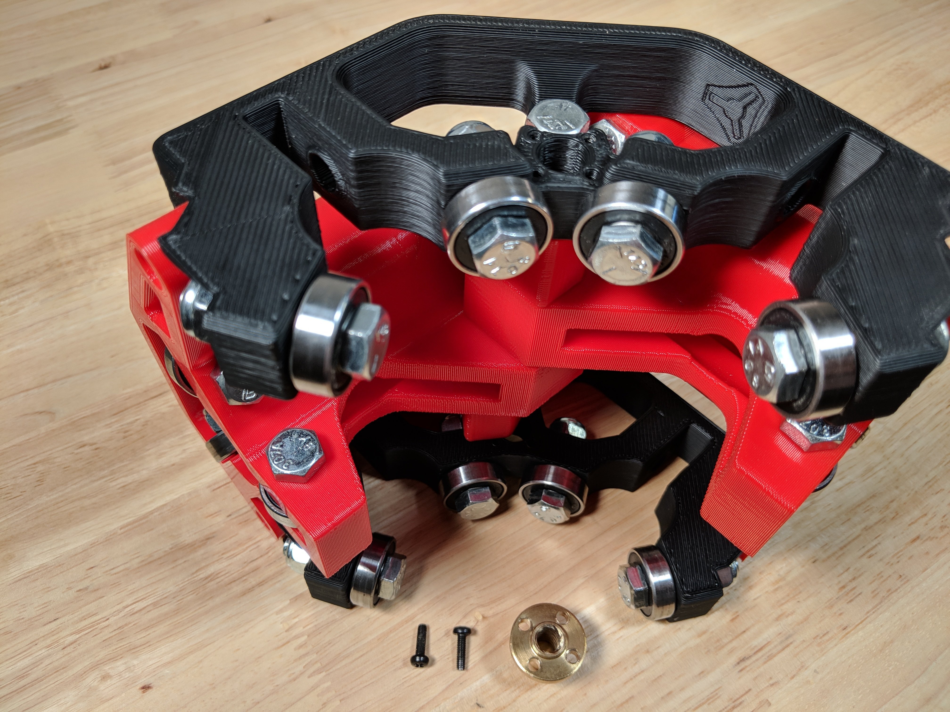
These screws only prevent the nut from turning no need to over tighten or fill all four holes.
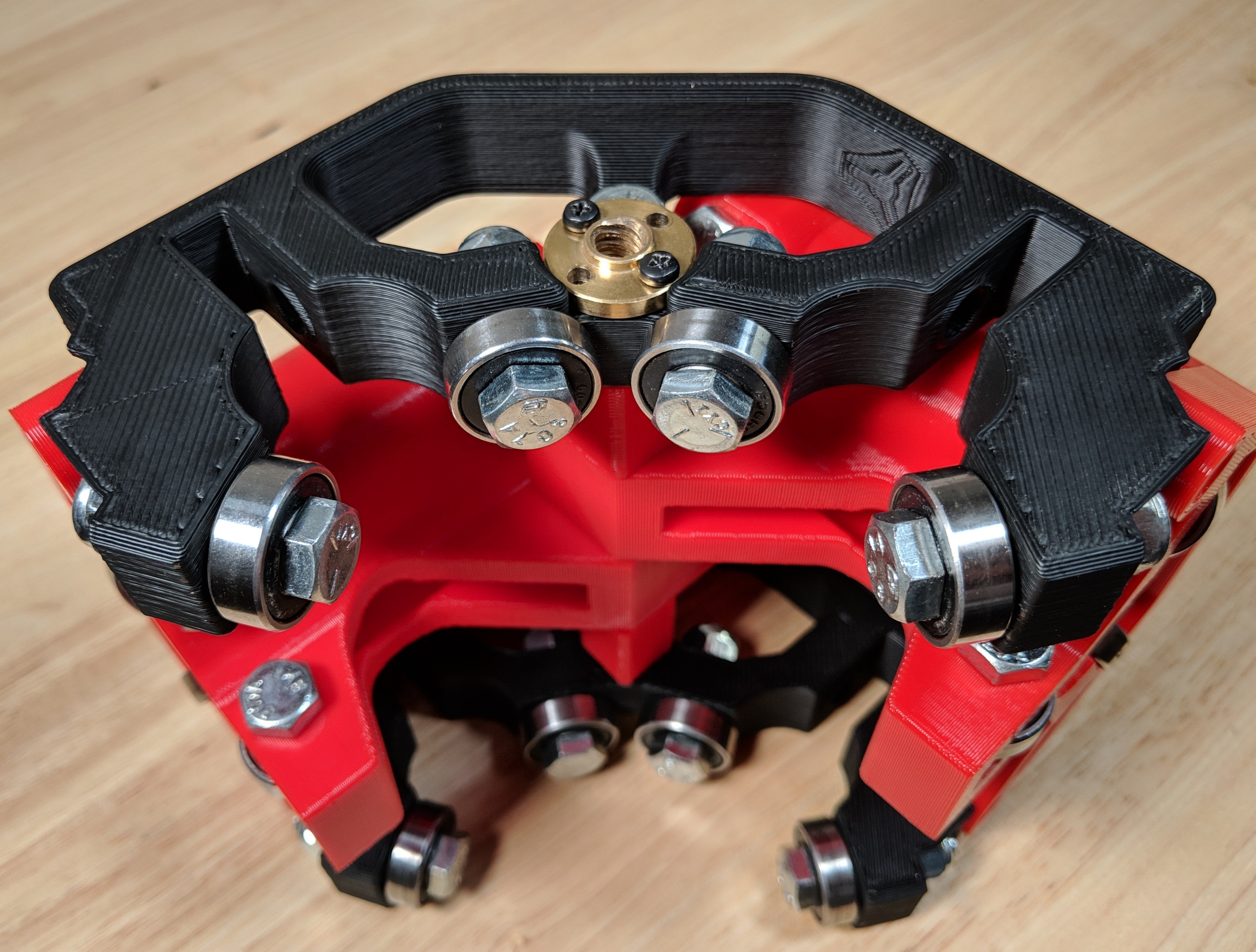
It is best to actually leave these a little loose to allow the nut to have better alignment with the screw. Seat them all the way and back off a half turn.
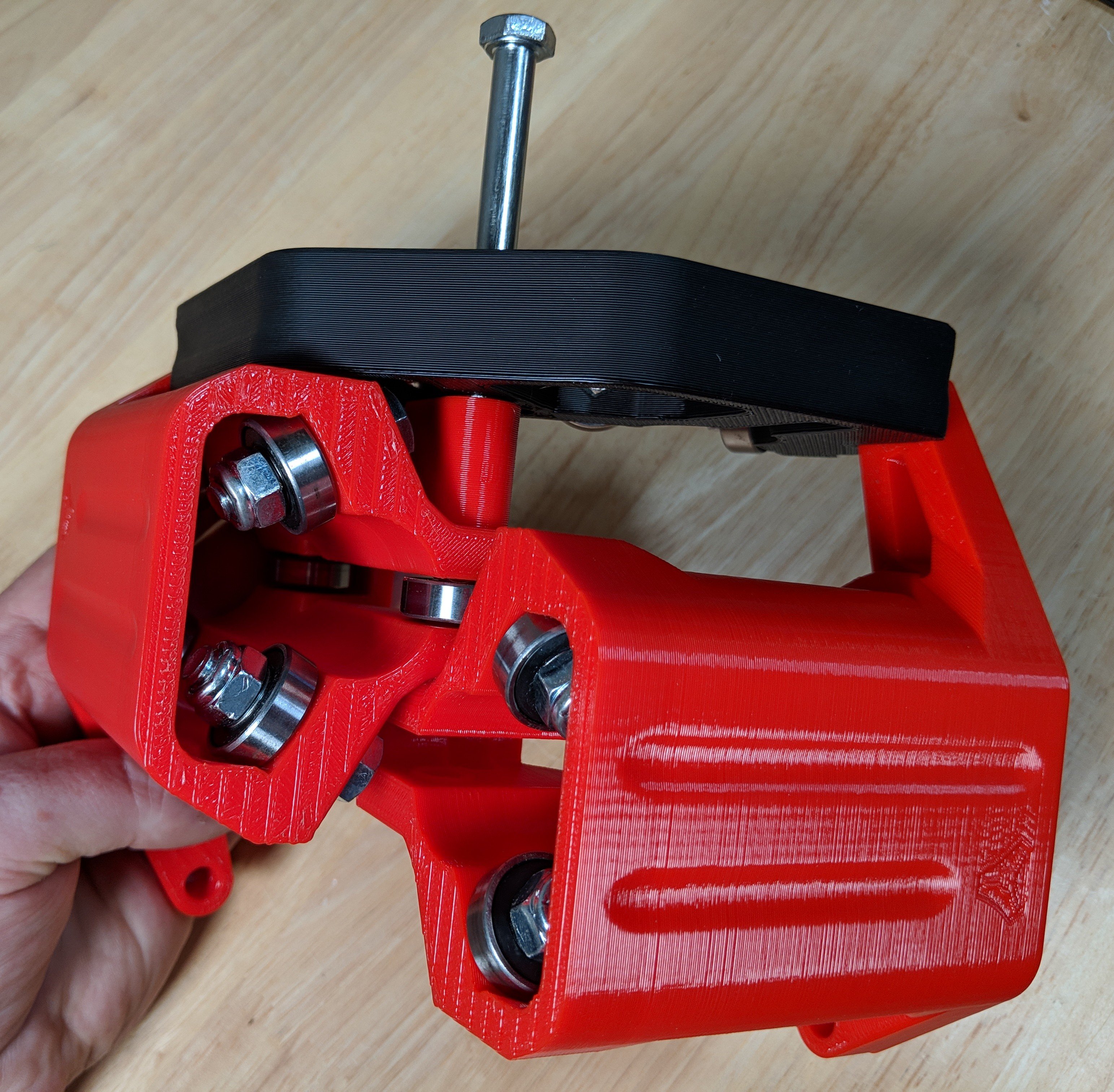
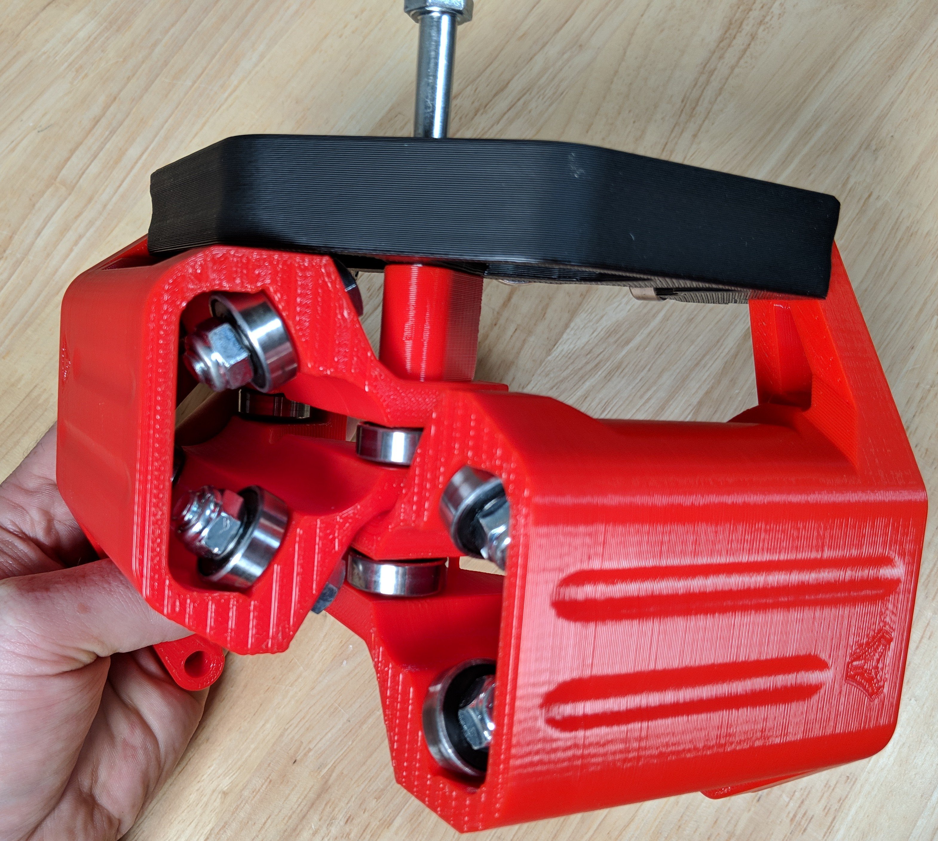
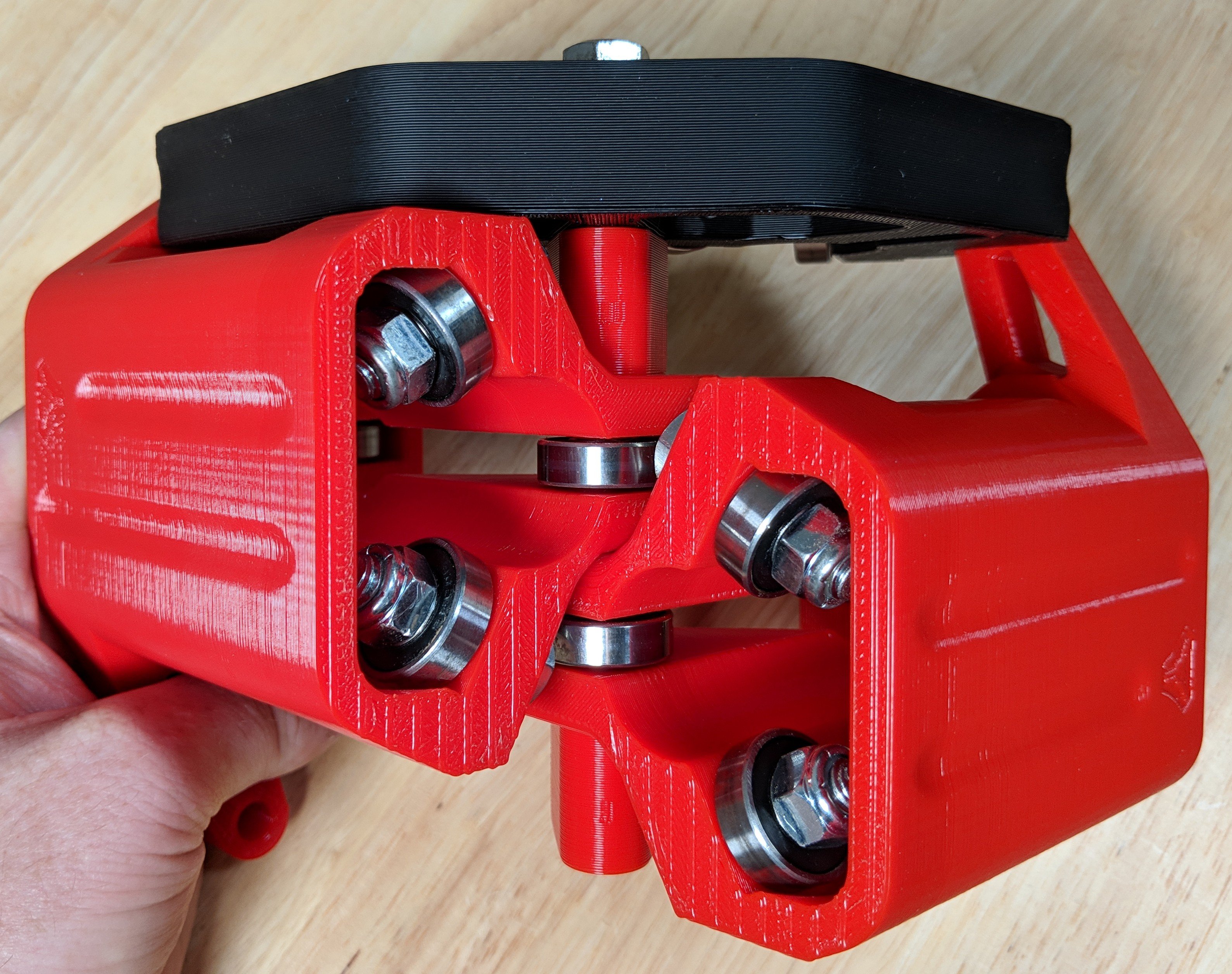
Tension Bolts C(x4)
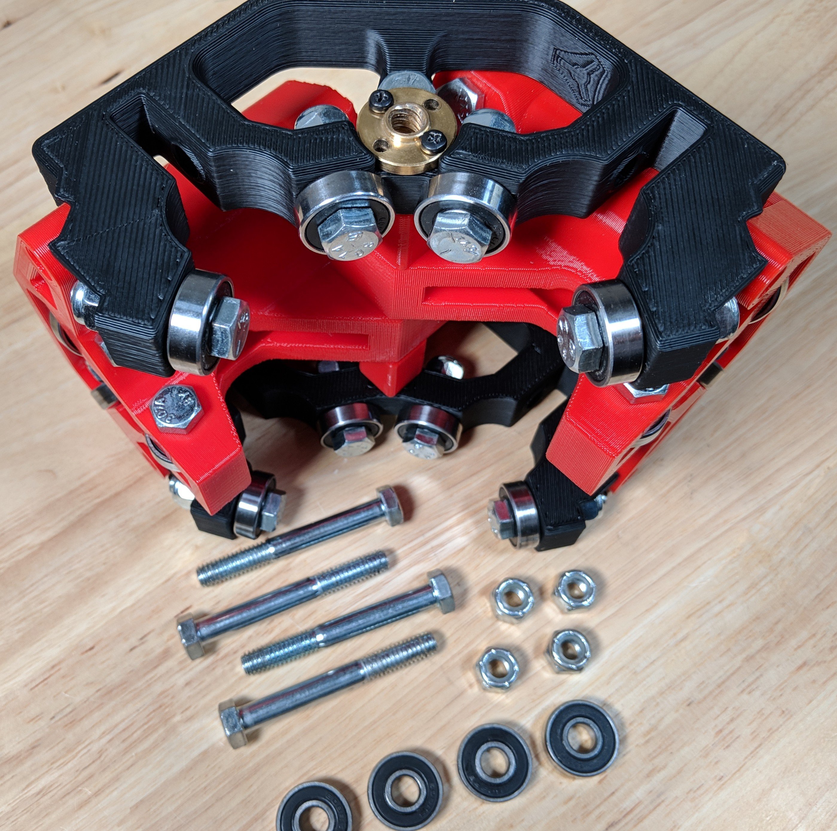
Use the 4, 2.5″ (M8 x 65) bolts, bearings and lock nuts.
These are Tension Bolts C.
These should be left extremely loose, just slightly touching the plastic.
Squaring
Now that the assembly is complete, this is the best time to double check to make sure the rails are perpendicular.
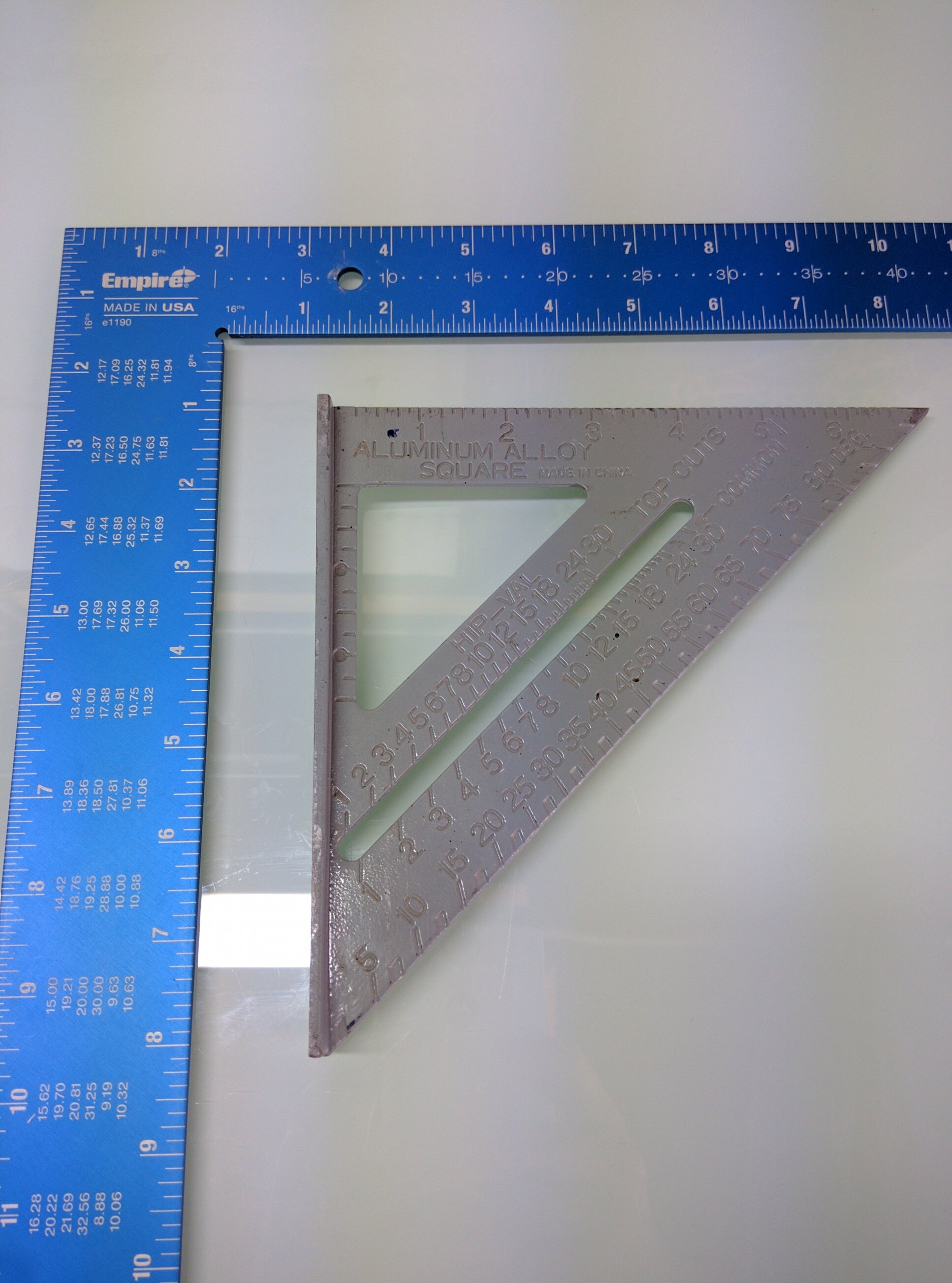
An inexpensive square works just fine. Both of the ones pictured were about $5.
Insert all 4 rails into the assembly (X, Y, and The Z assembly).
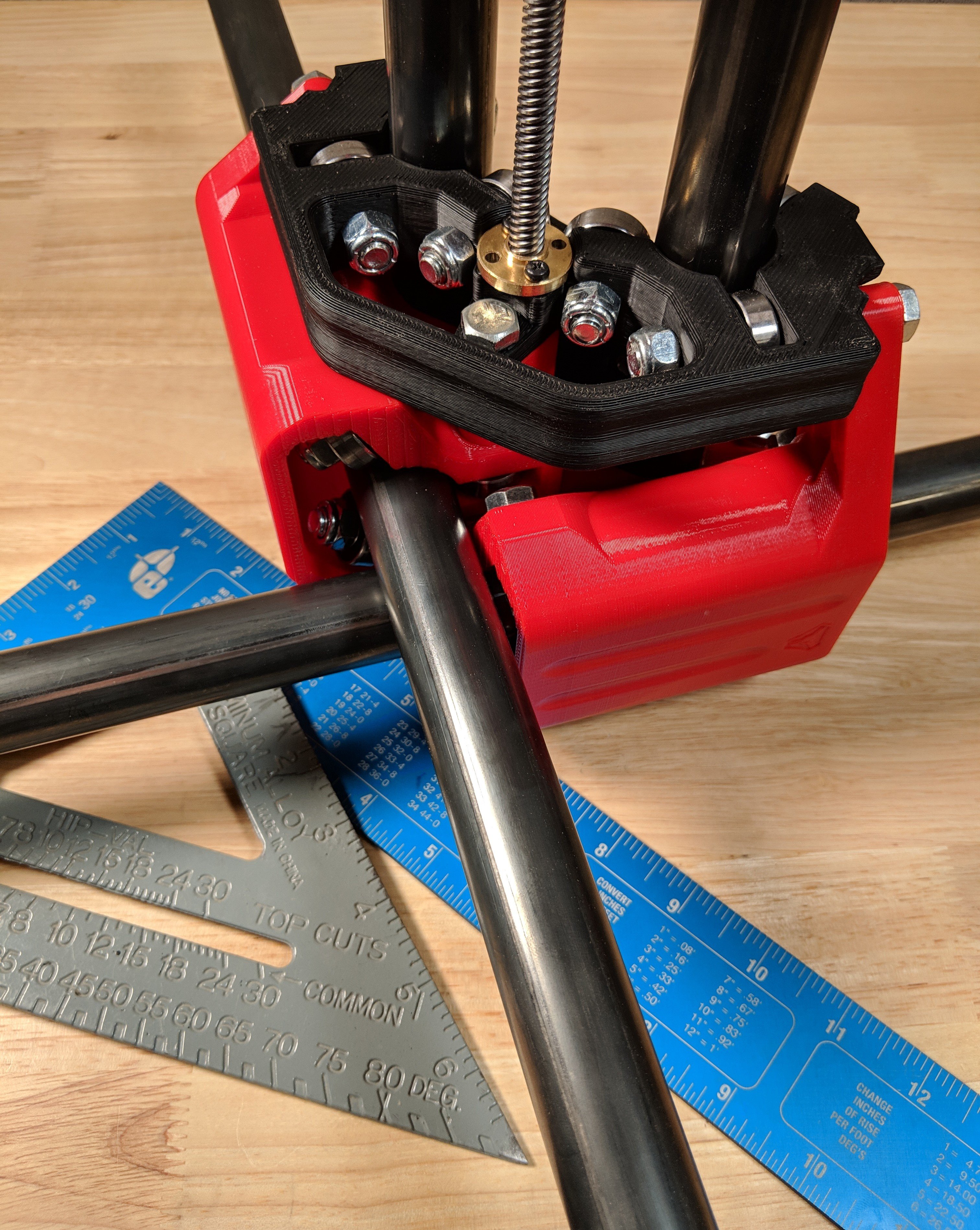
- The least amount of tension on the rails is best.
- At this point, with all the tension bolts loose the rails they should actually be a snug fit, if they are not post some pictures in the forums so we can help.
- Tension bolts “C” should have the locknuts and the bolt heads tightened so they are just touching the plastic. Equal light tension keeps the Z axis perpendicular to the work surface and locks the assembly together.
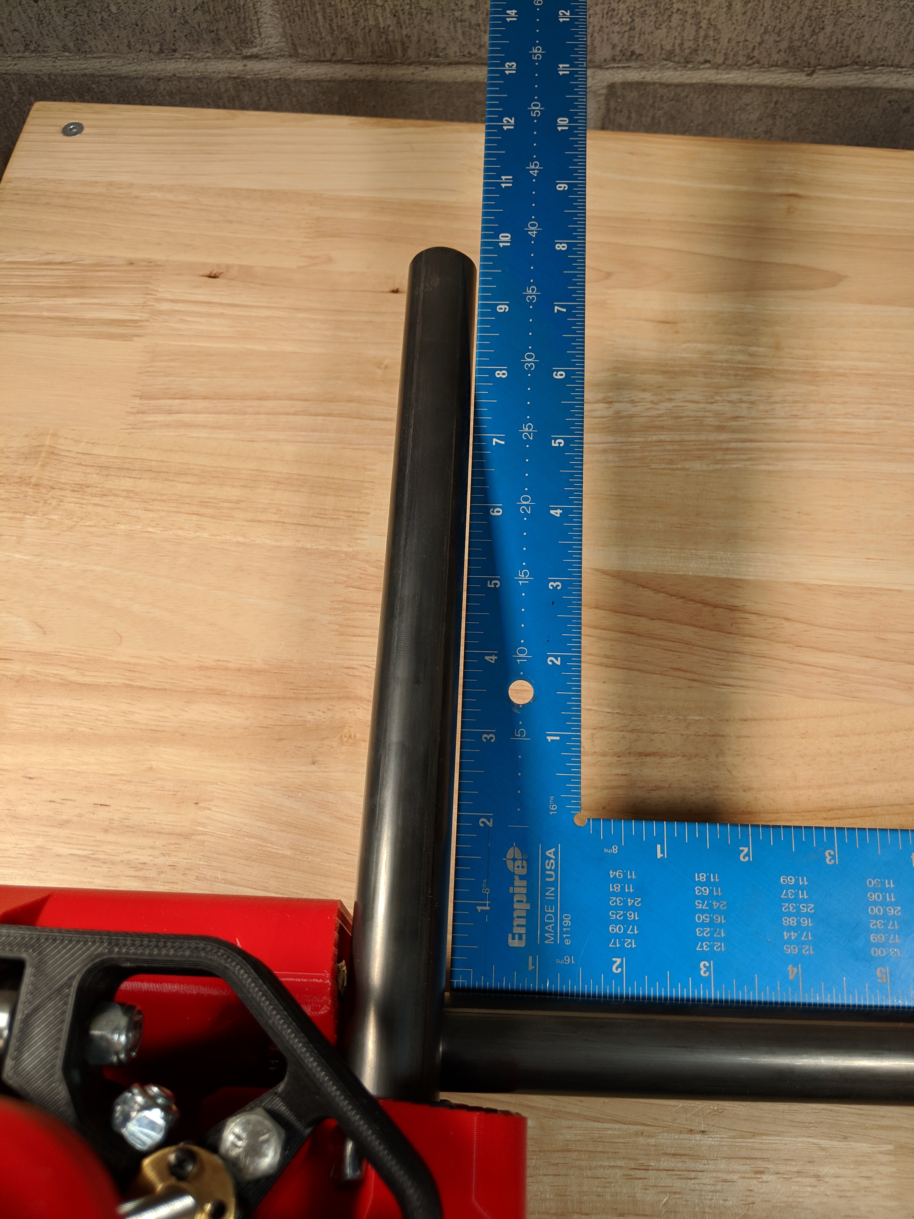
- Use a square to see if your XY rails are, perpendicular.
- You can tension bolts “A” and “B” to adjust the rail angle. It is best to adjust by loosening them. If they are already loose tightening them slightly moves the rail away from the tension bolt.
- I’m sorry there is no magic bullet for this part. For most people this should go together square as is, but if you are having issues you might just want to run it as is for a while and then try again after it has been broken in a bit. You cannot really do this in the rollers so any adjustments should be in loose rollers or apart to this stage.
- This part can be tricky for some, take your time. Small adjustments.
TIPS
-
Lube the lead screw.
-
If you are new to all of this, don’t worry about perfect here yet. Most people never even know or care how perfectly square there machine is. Carving a name into a piece of wood no one would notice if it is a 32nd of a degree off square. Have some fun learn some things, you can always come back to this later.
-
Using the blue square picture as reference, assuming Tension bolts A and B are all the way loose. Tightening B (the long one) would make the angle smaller as shown on the blue square. If instead you tightened both A bolts a bit the angle should open up.
-
If you run into Z axis perpendicularity issues later on it usually means your C tension bolts are not equal. Tighter on top pushes the rails away from the bolt, as well as the bottoms. A square from the work surface to the Z rails can test this after full assembly.