Z Axis
Important
Please do not attach anything to this assembly above the tool mount. You will see lots of images of people attaching cable chains, wires, and vacuum hoses to the motor mount. This is the absolute worst place on the entire machine to attach anything! It will act as a torque multiplier and completely ruin your accuracy/precision. Anything necessary should be attached to the main gantry assembly there is lots of room on the XYZ piece.
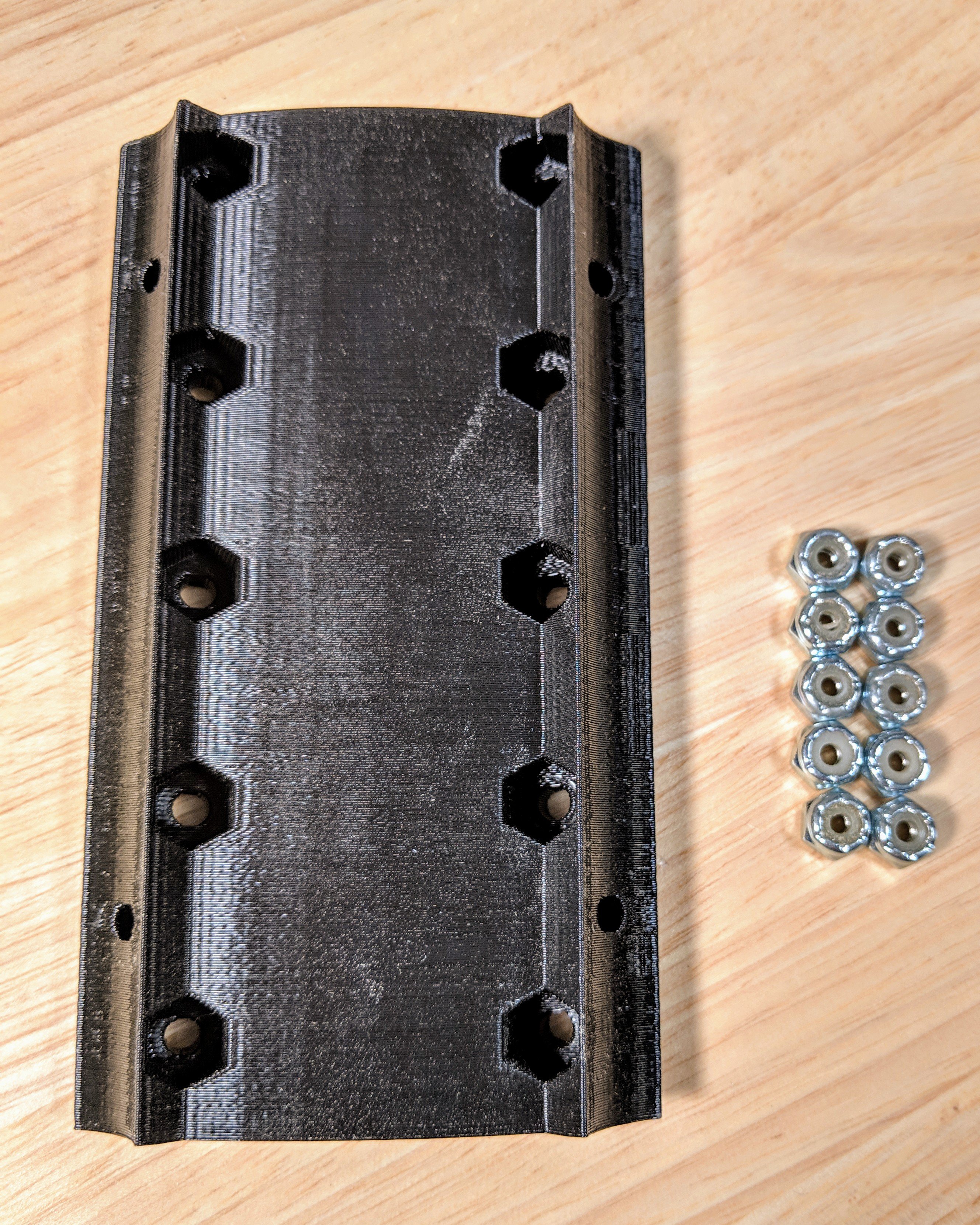
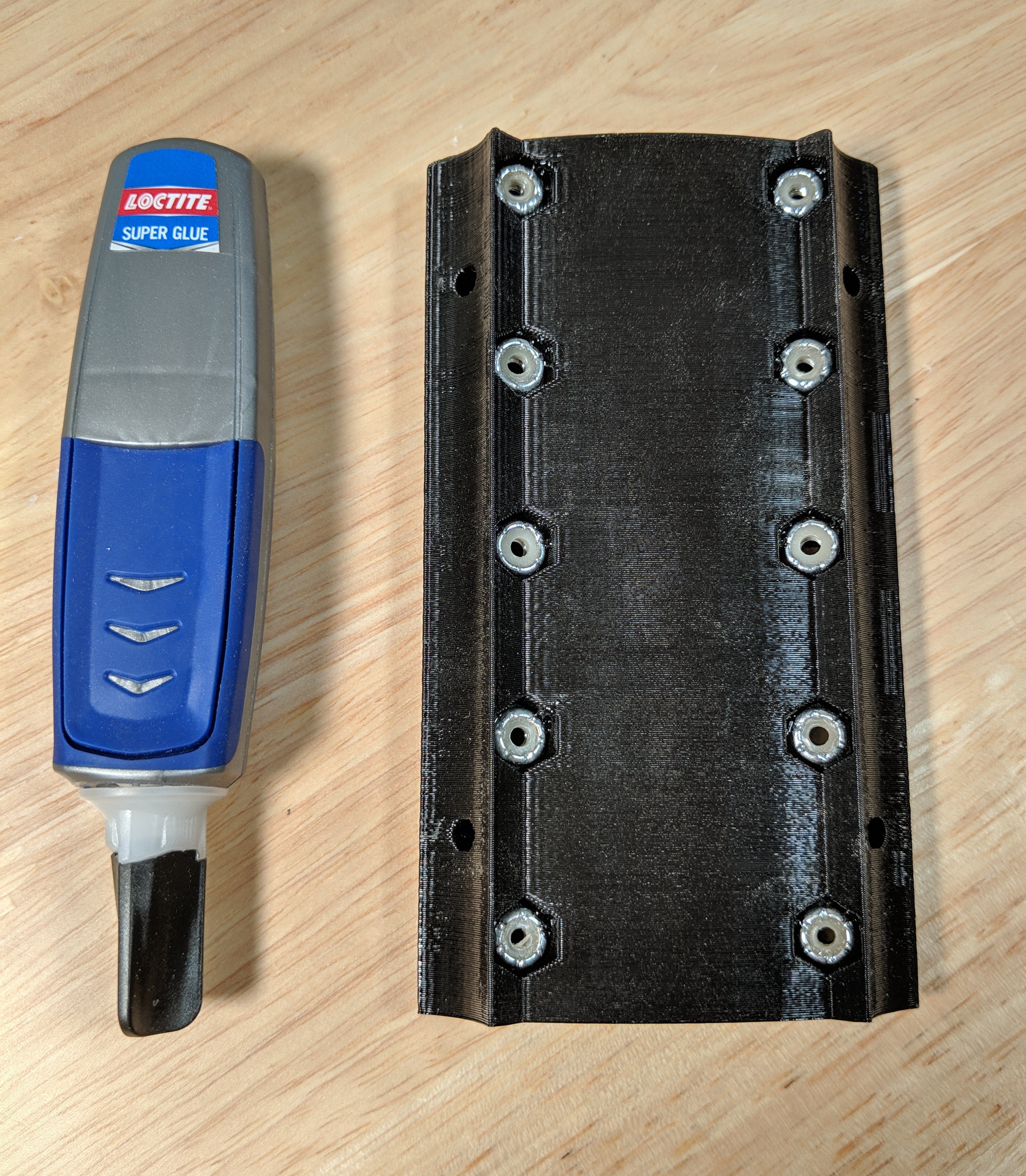
The tool mount piece uses either #6 lock nuts or M4. Insert the nuts facing the right direction and if they are not a snug fit a tiny drop of glue in the corner will keep them from falling out. I add one after they are inserted right at the corner of each nut just to be safe. I use cyanoacrylate gel. It is not doing anything other making sure they do not fall out when not in use, if they are in use they do not depend on the glue at all.
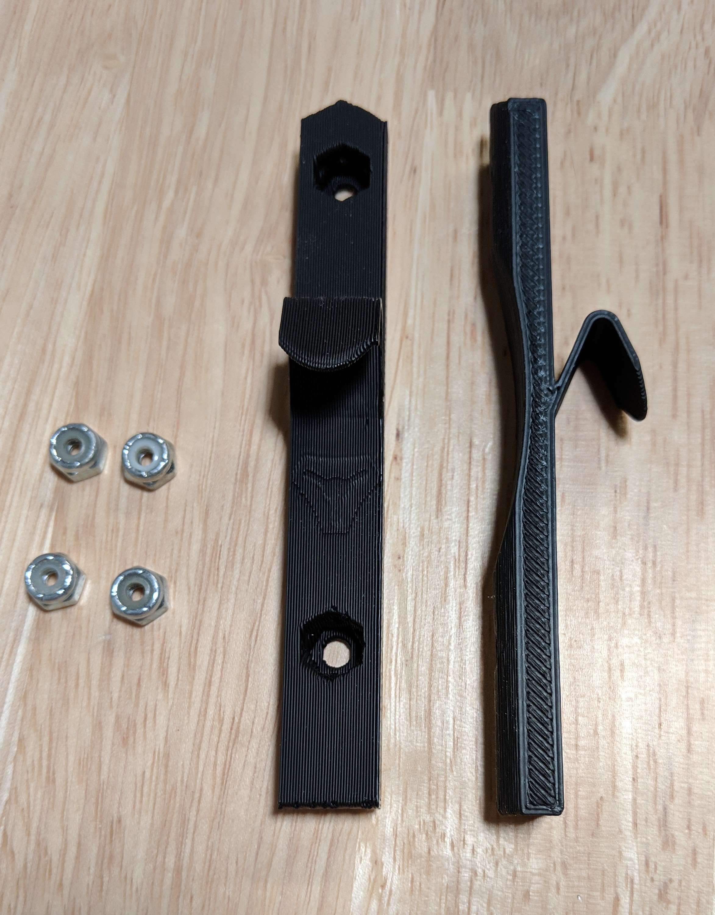
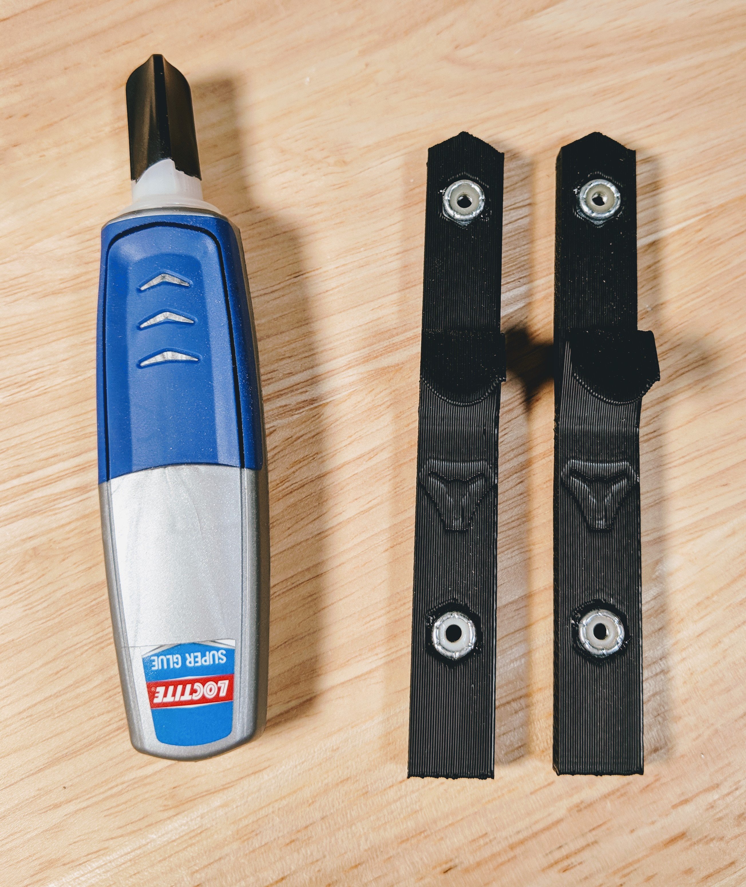
Insert the 4 nuts into the nut traps, if they aren’t a tight fit a drop of glue here will help in assembly later.
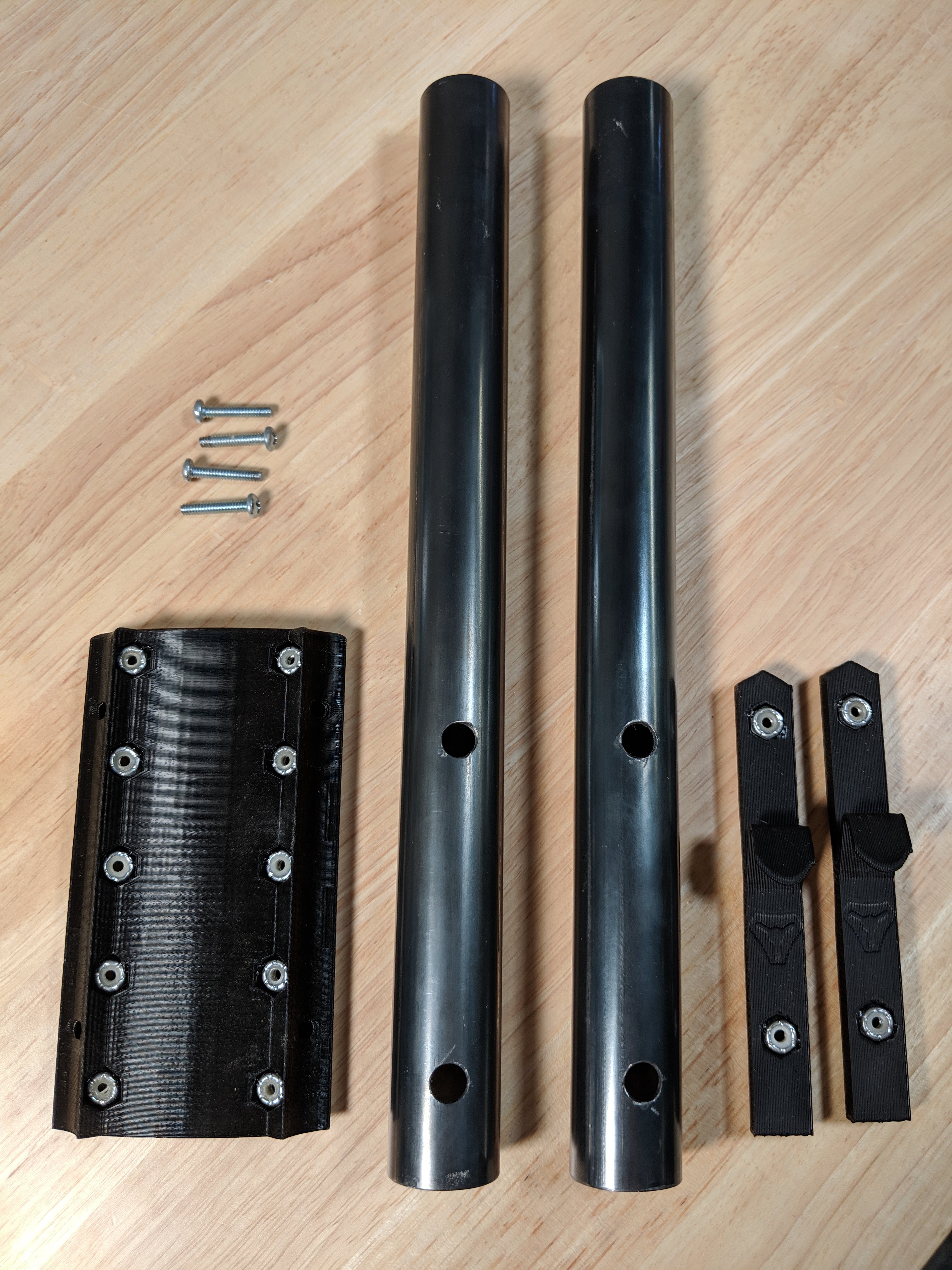
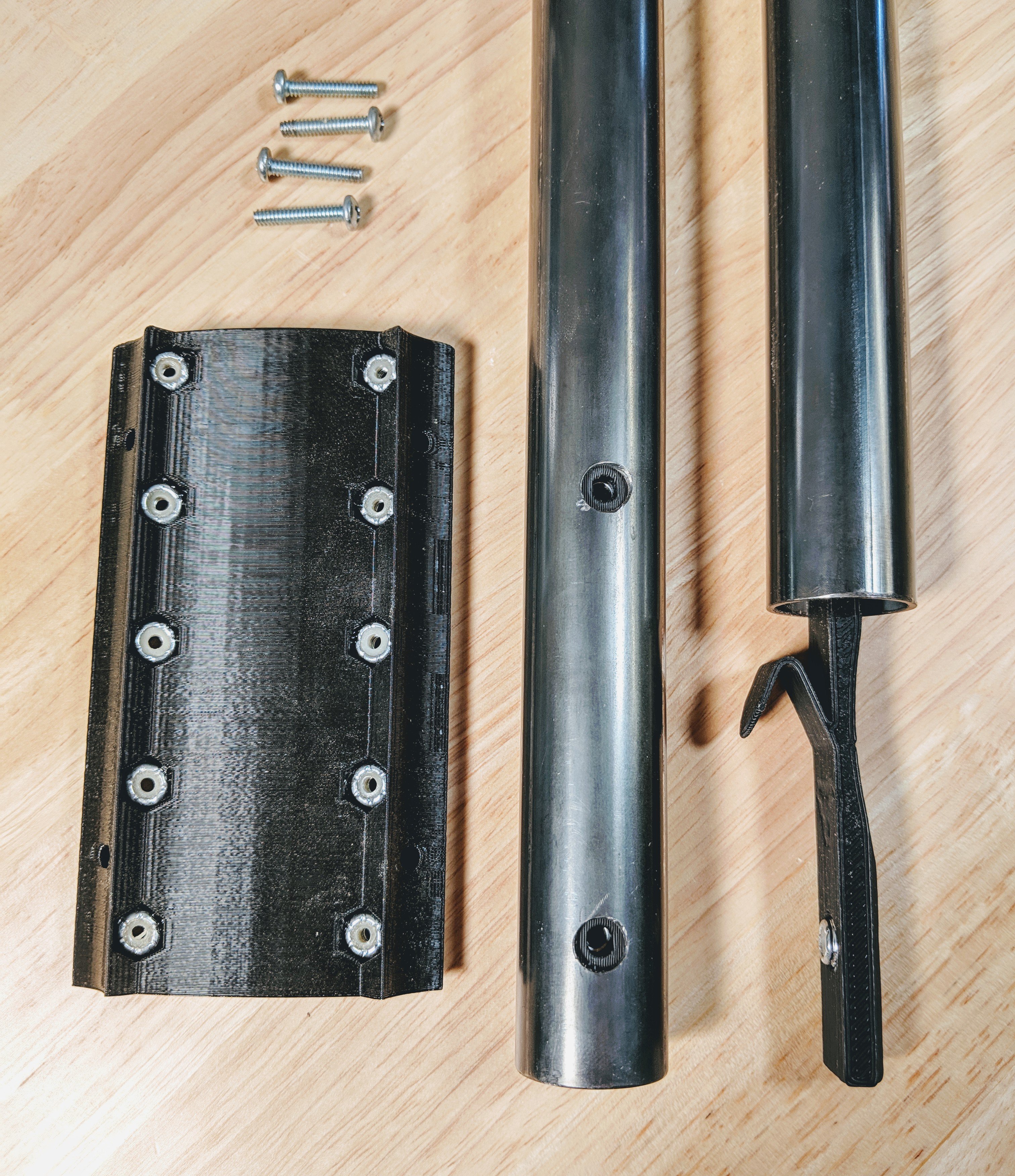
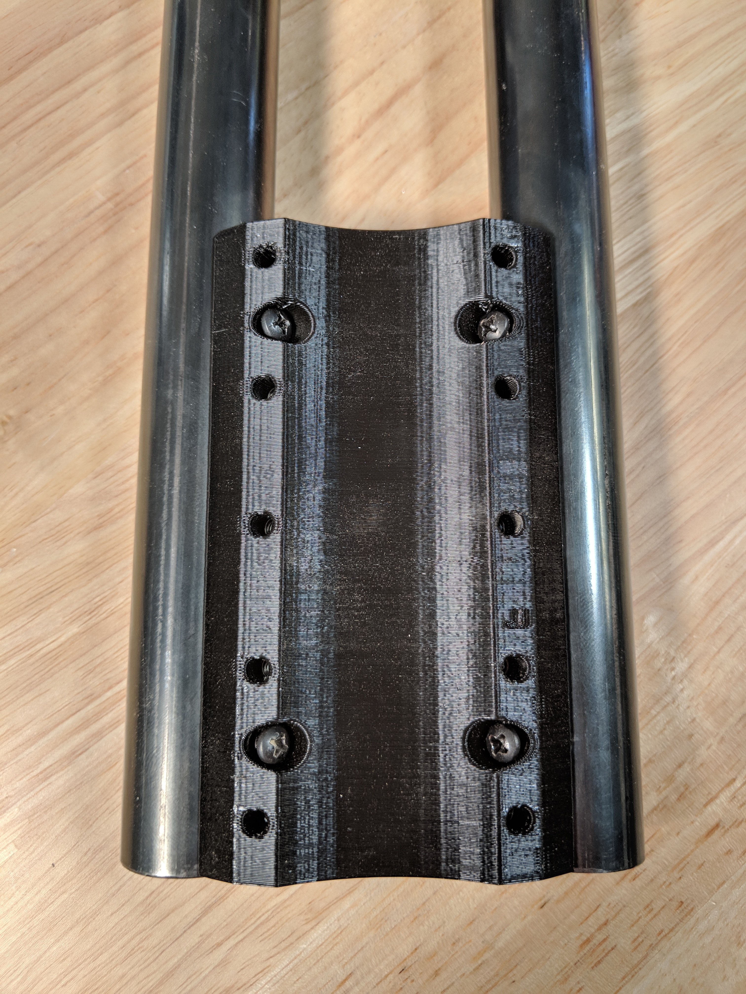
Insert the nut traps into your cut and drilled Z rails, pointed end up. Align the holes. Get all four screws ¾″ (M4 X 20) started but leave them extremely loose for a later alignment step.
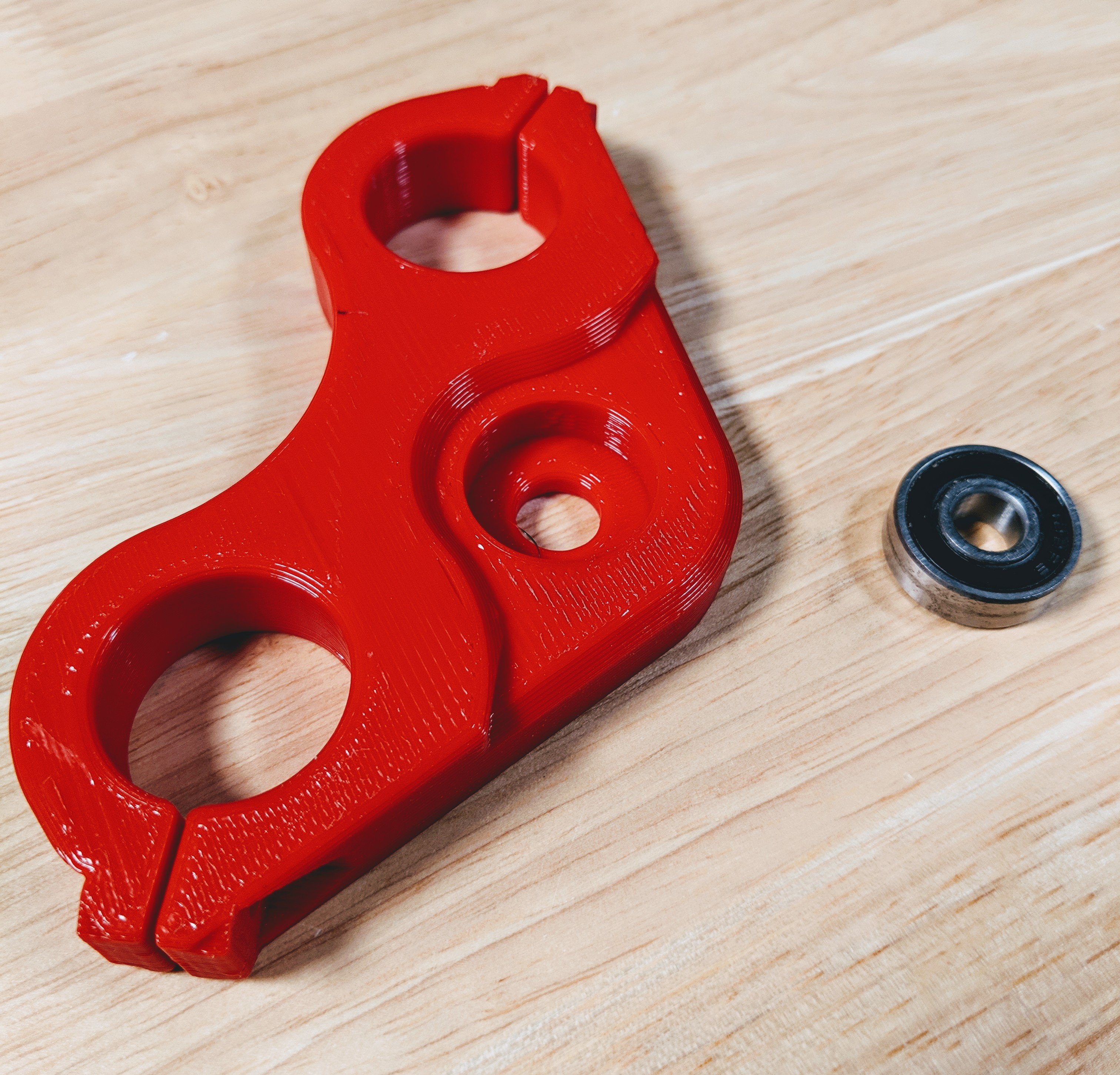
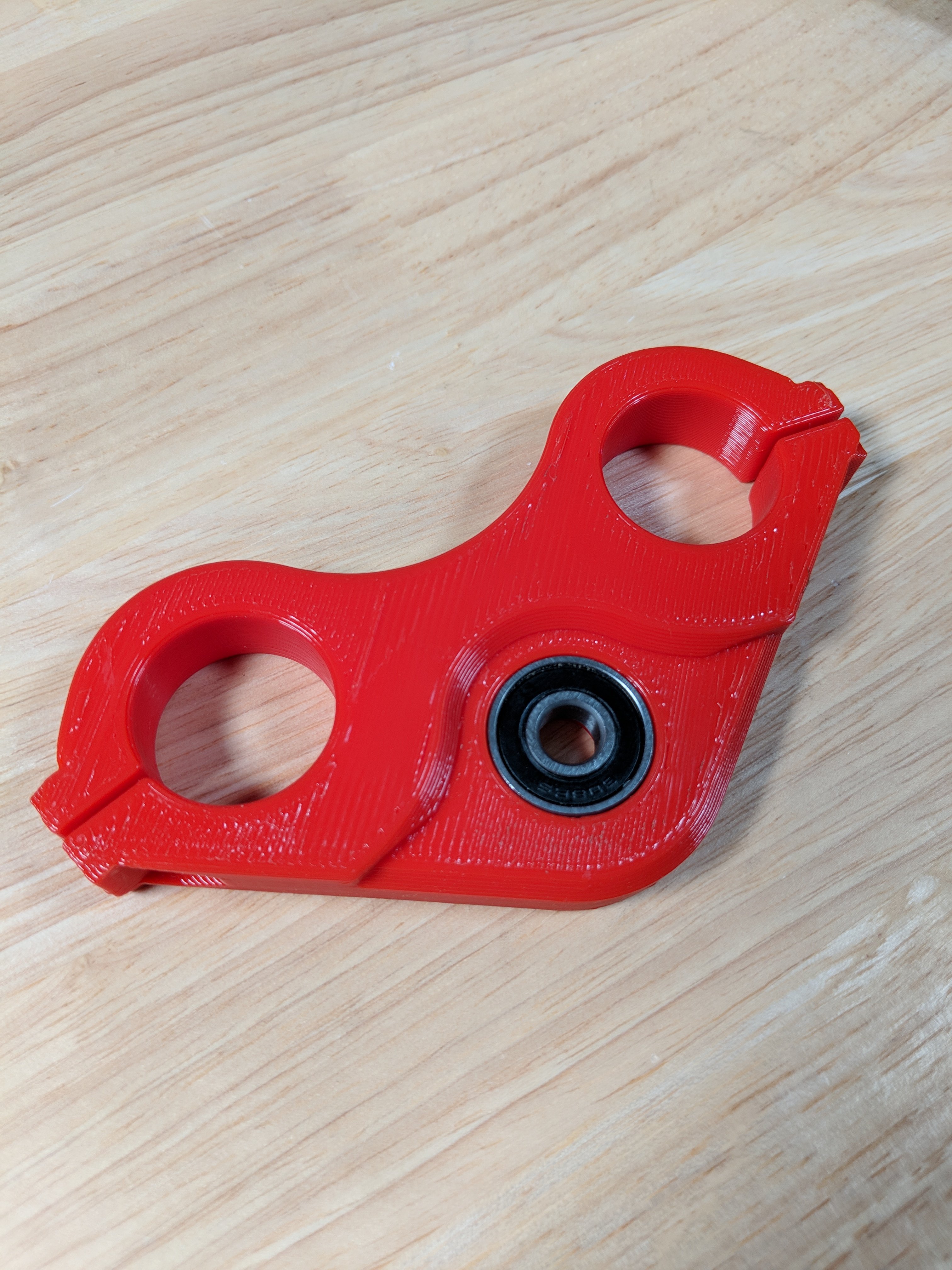
Press the bearing into the Z-Lower bracket. Make sure it is seated all the way and not crooked.
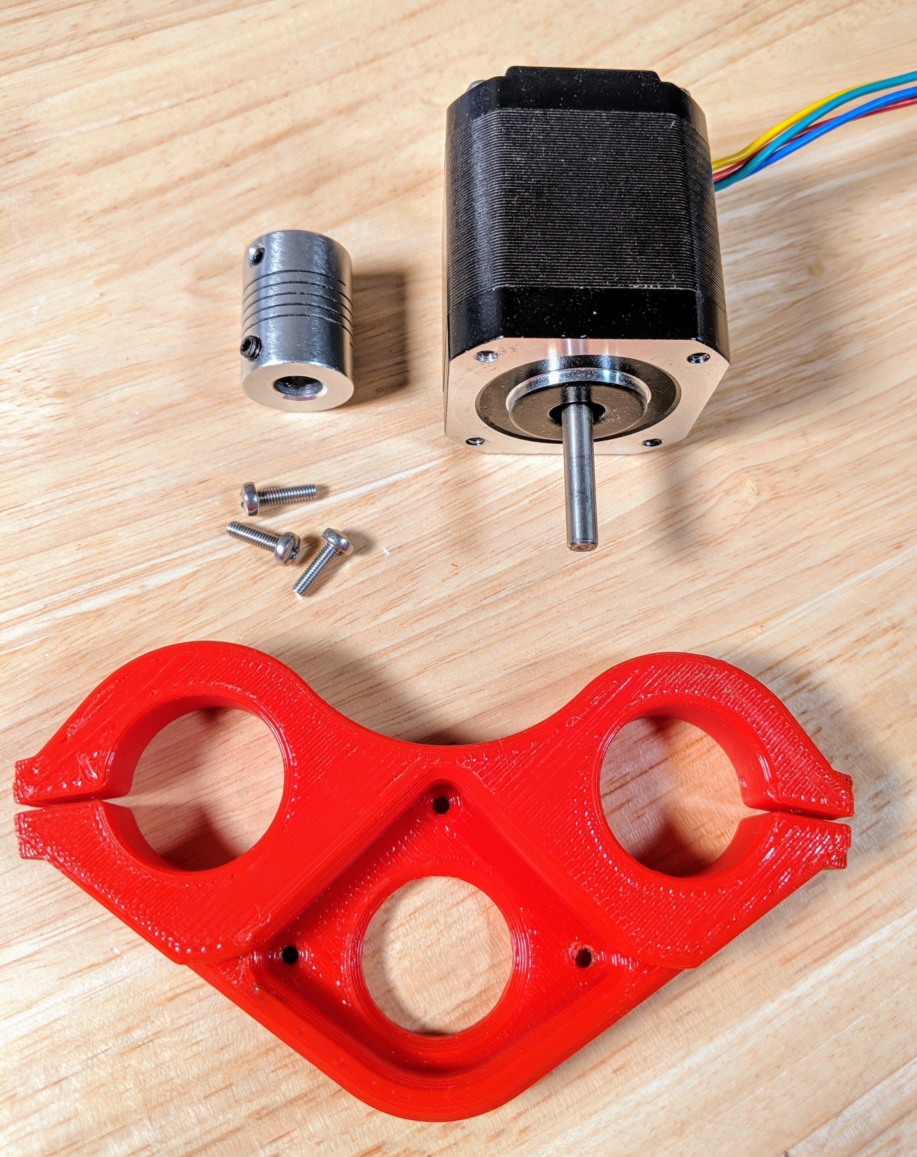
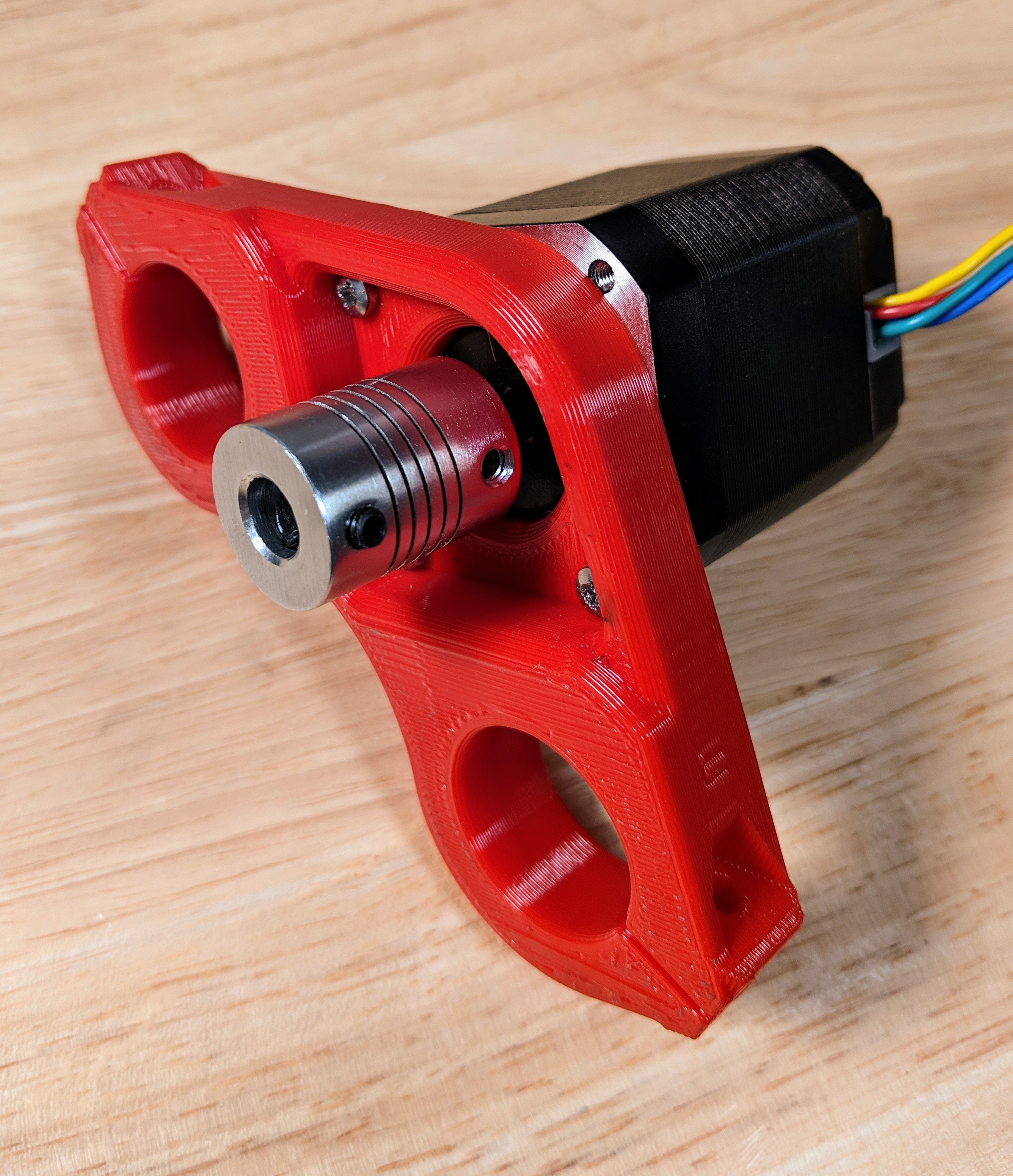
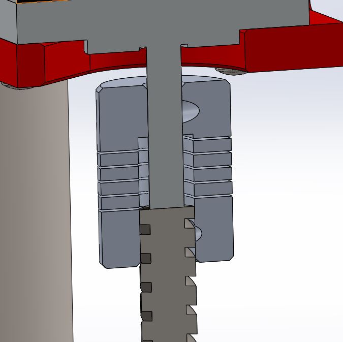
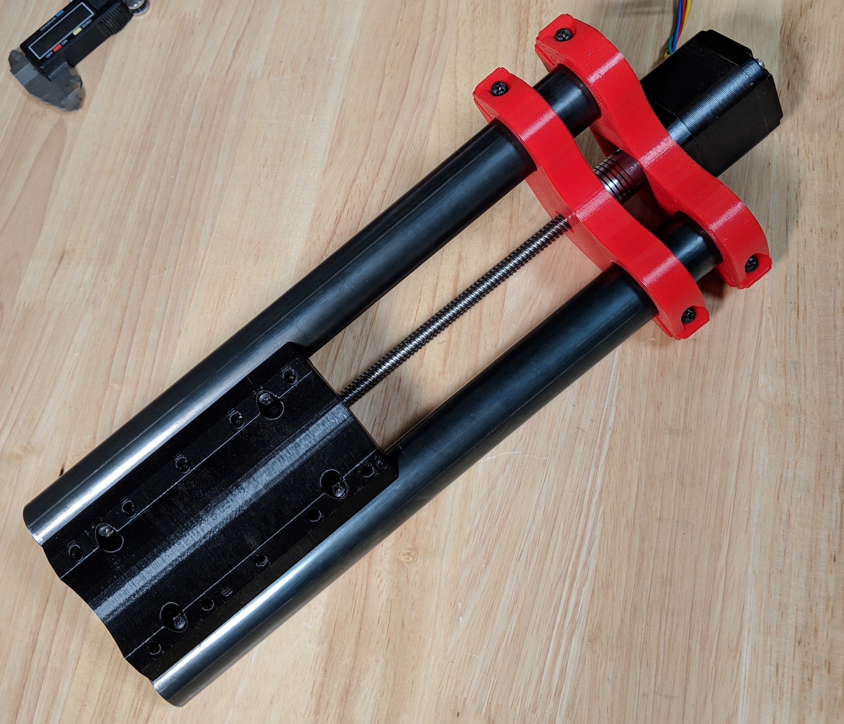
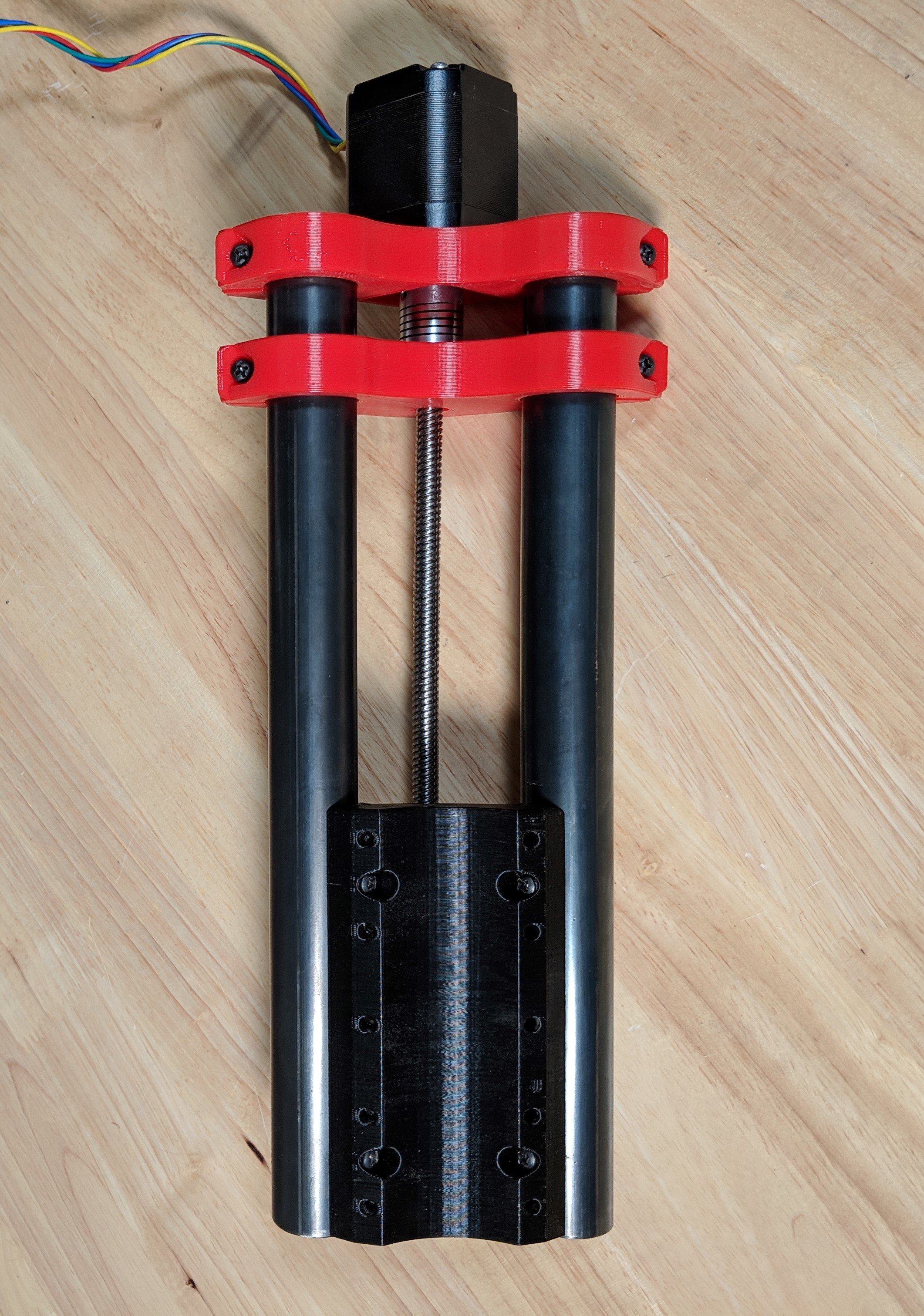
Tighten the coupler onto the shaft, first tighten grub screw on the stepper shaft flat spot, then the grub screw on the round part. Make sure the shaft is most of the way into the coupler as shown in the cutaway. Use 3 M3x10mm screws to attach the stepper to the Z-Motor bracket.
Do not insert the Lead Screw yet. The picture is to show you how far the shaft should be set.
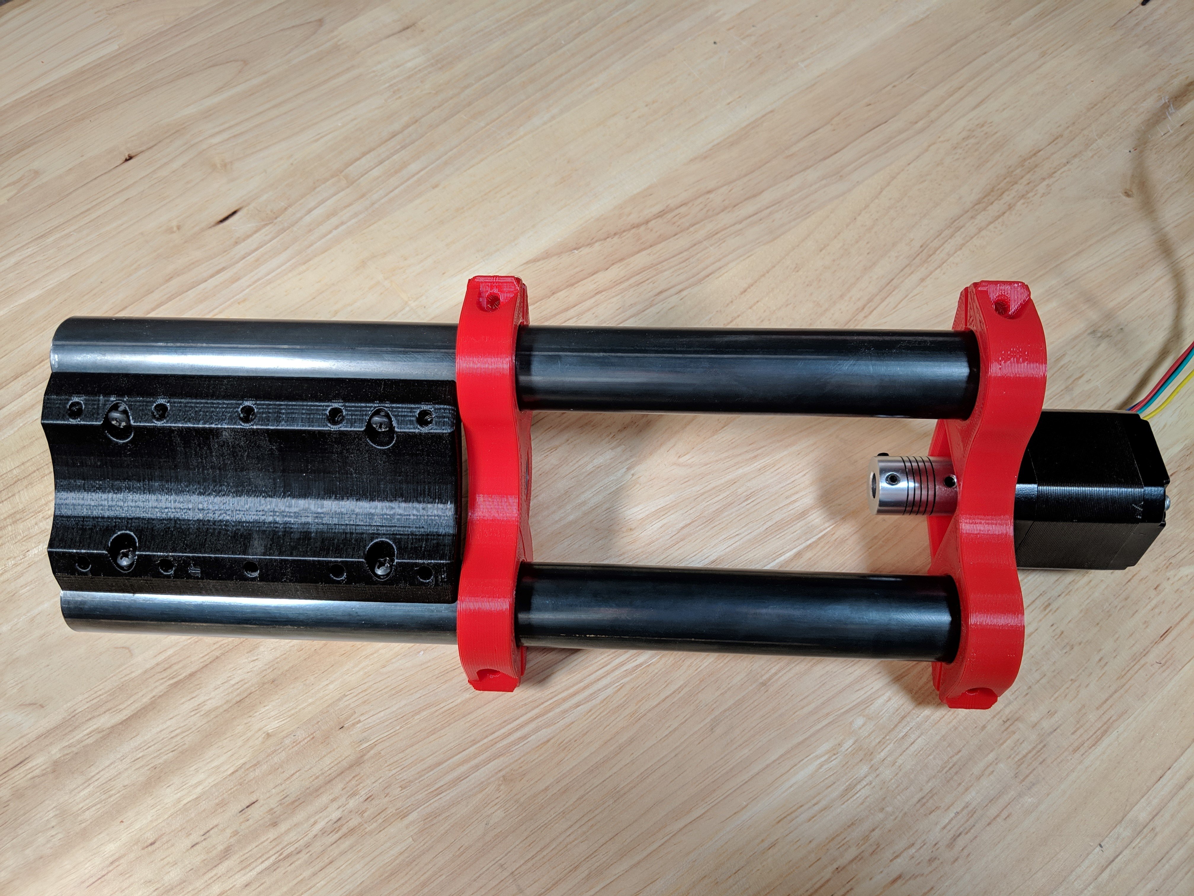
Use no screws on the Z mounts yet. Slide the Z-lower bracket onto the z rails open bearing side will face away from the tool mount. Slide it all the way to just above the tool mount. Next add the motor mount. This step lets you align the rails and snug up the tool mount 4 screws ¾″ (M4 X 20). Snug, if you hear a crack you went overboard.
Slide the lower tool mount to where it just touches the coupler but does not compress it at all.
IMPORTANT STEP
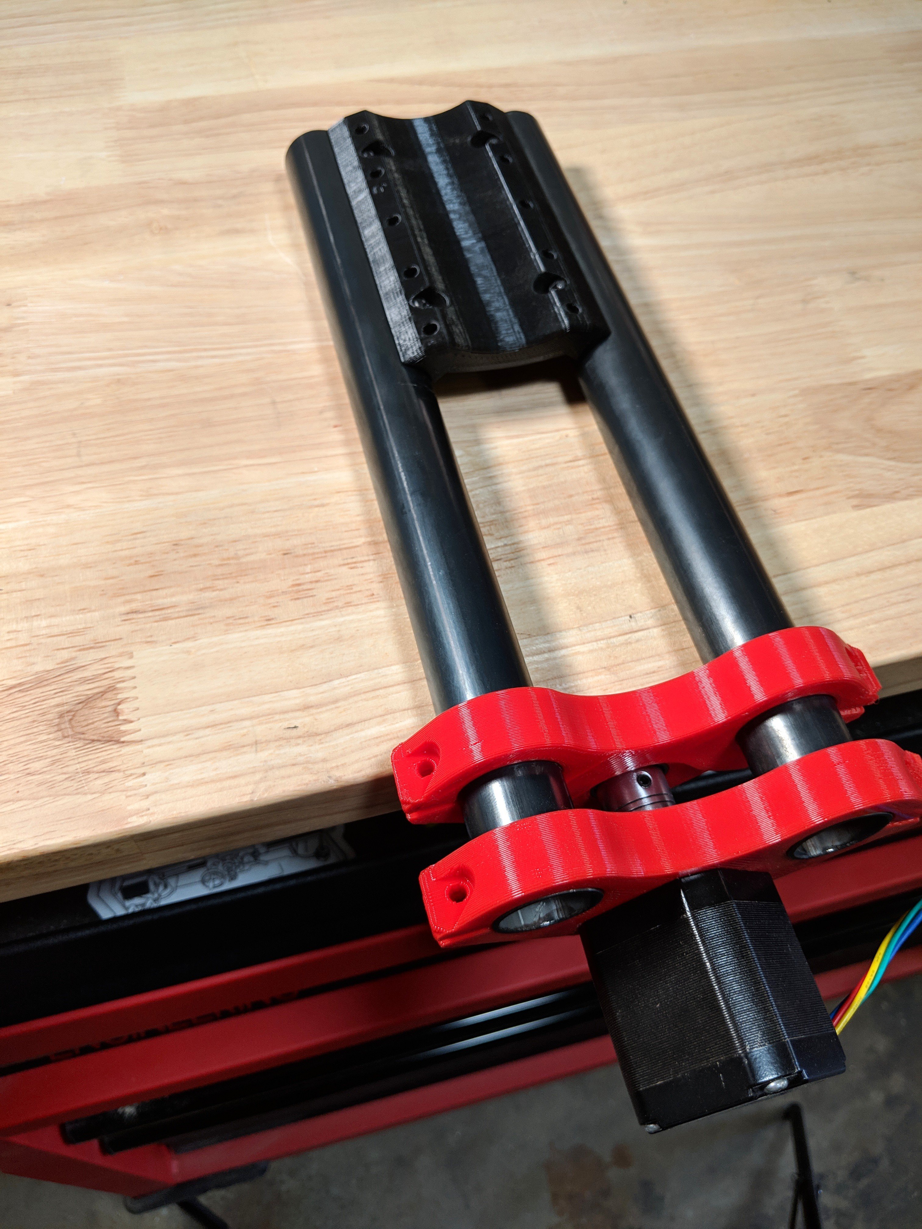
Make sure the coupler touches the bearing so it can support the weight of the tool. We are using the ball bearing as a thrust bearing (not the right type of bearing but it is a tiny load).
At this point hang the assembly off the edge of a table. Make sure the rails are sitting flat on the table, if it is not loosening, push down on the rails, and tighten the tool mount screws. If the rails are twisted it will rock back and forth…that is bad.
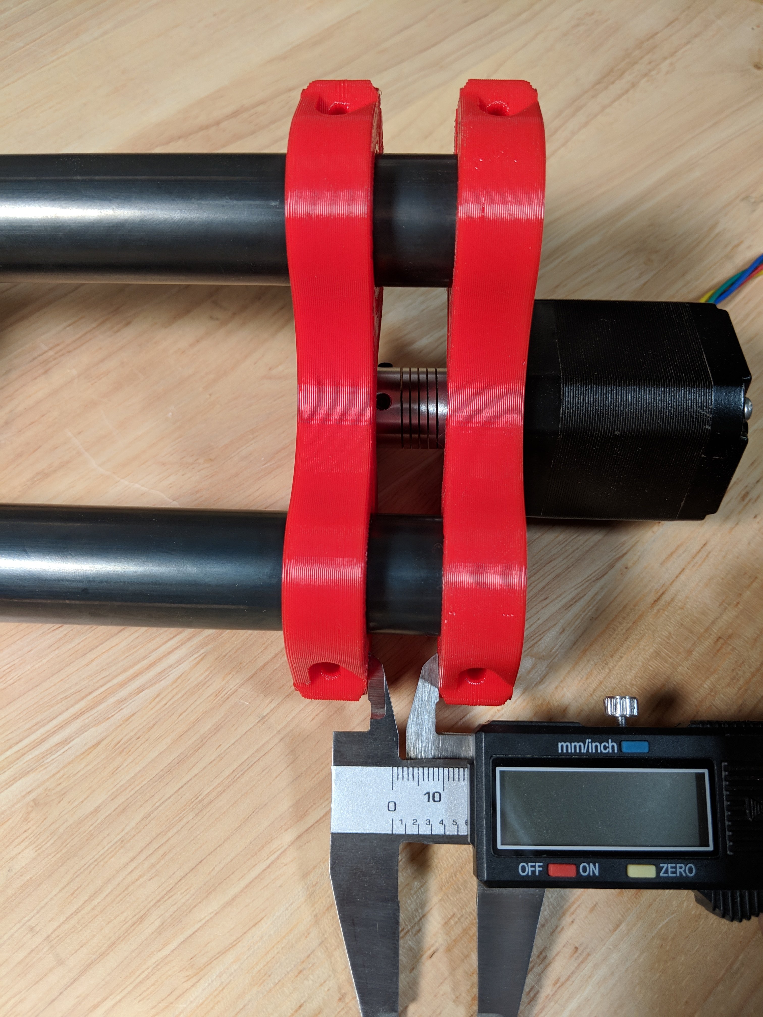
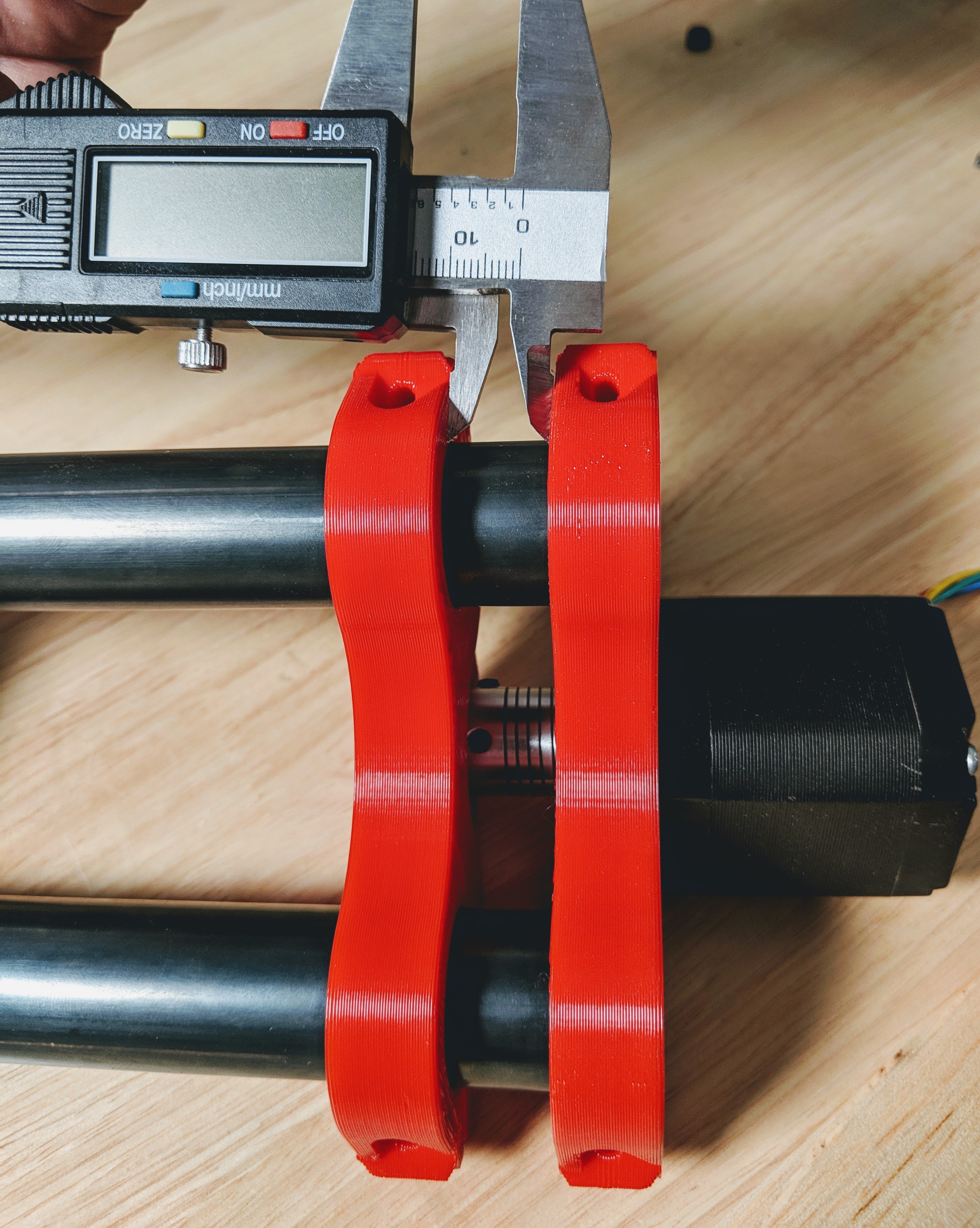
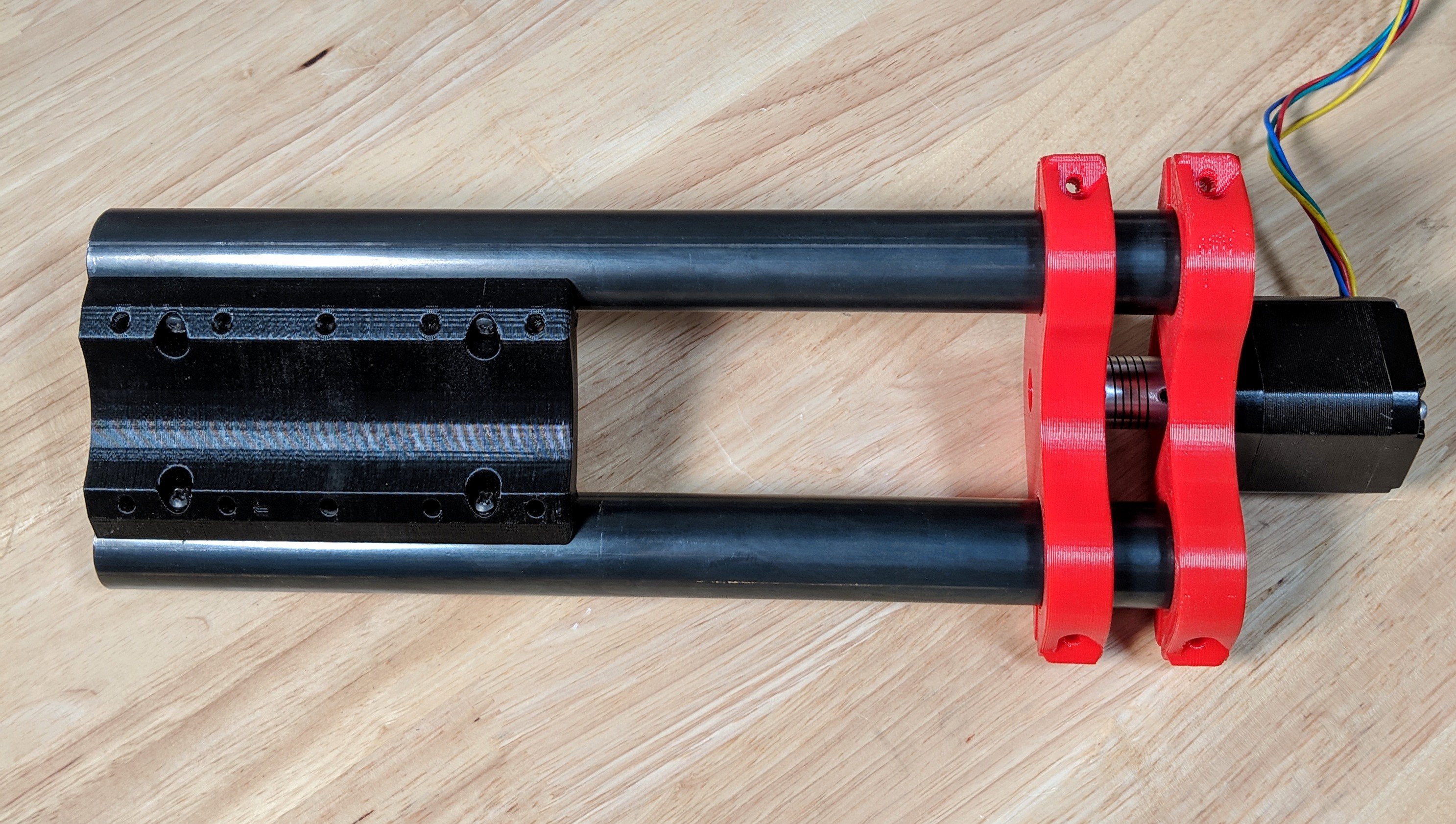
Try to get the gap between mounts to be relatively equal while still touching the coupler and bearing. This dimension will be different for every build. Check again, are the rails still flat?
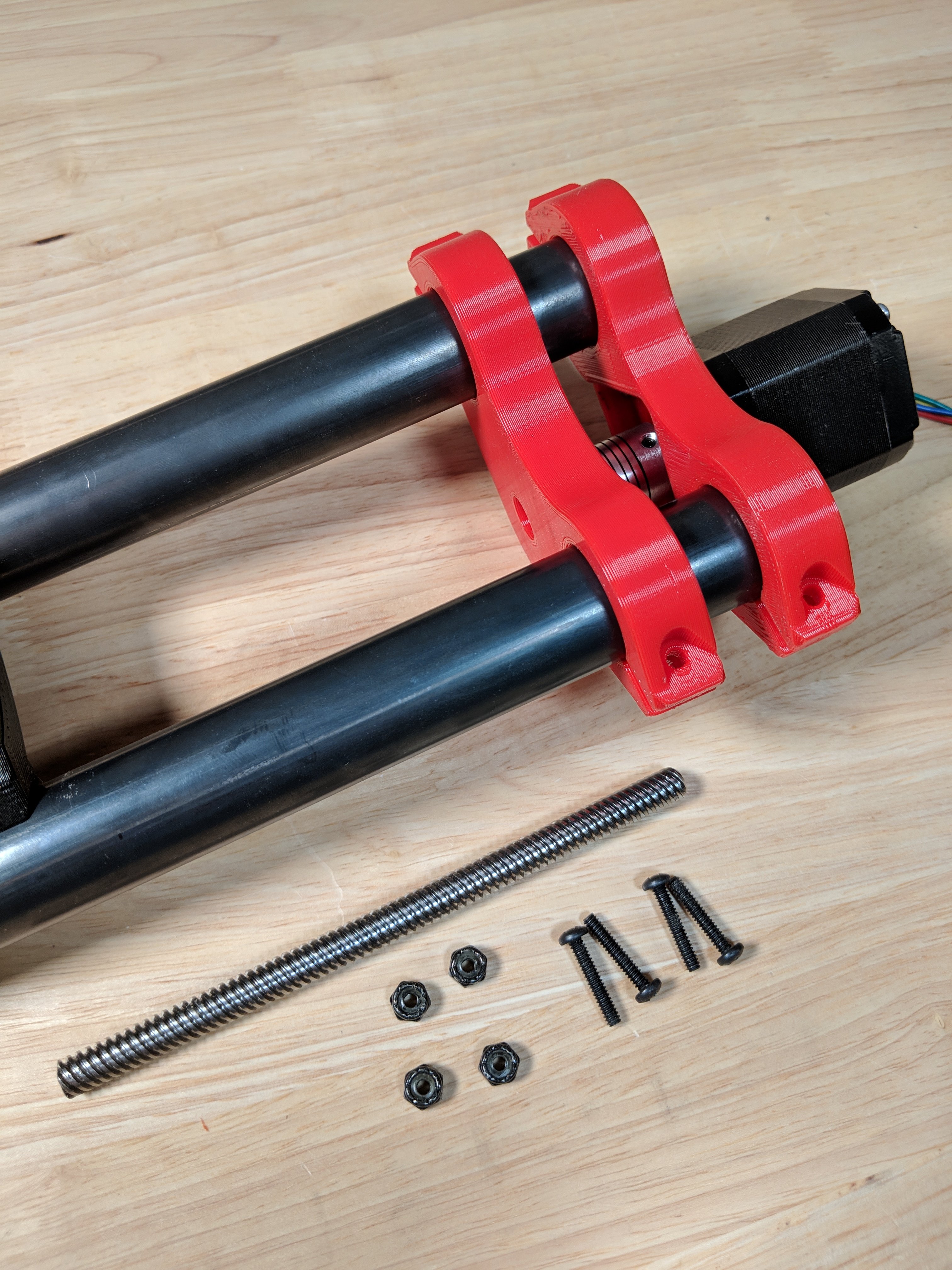
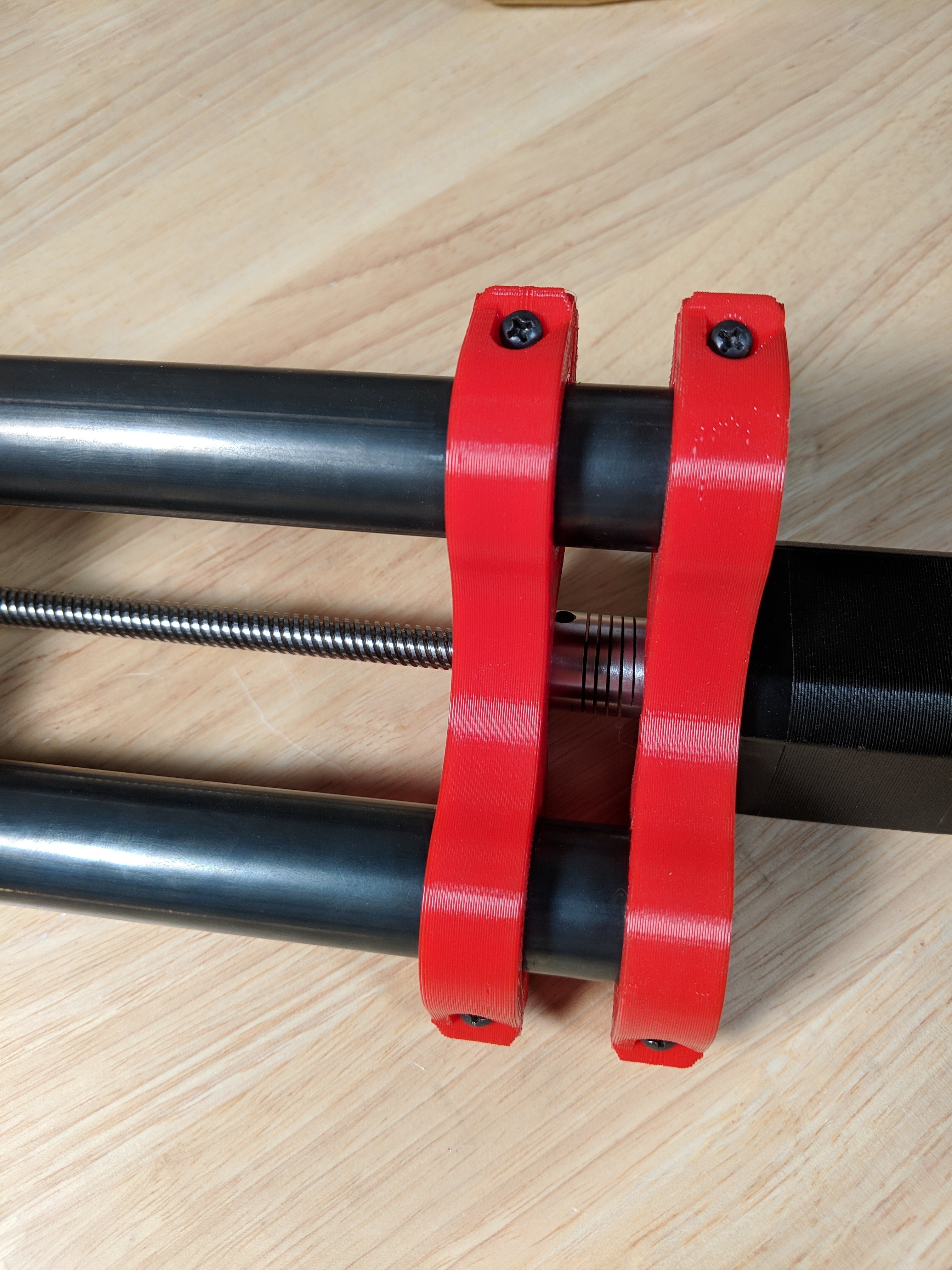
Add the screws ¾″ (M4 X 20) and nuts to the Z brackets, snug slightly.
Snug slightly means, less than you think. If it is too loose at some point the mounts could move up and is very easily noticed and is easily fixed by going a very tiny bit snugger. If they are too tight you will crack the mount, not easily fixed. Err on the side of too loose.
Check again, are the rails still sitting flat? Add the lead screw into the coupler. The lead screw should touch the motor shaft to fight thrust in the other direction from the lower mount bearing. Again, not the best engineering solution but it works great with this light load. The lead screw should be at least as long as the calculator specifies, but no longer than the bottom of the Z rails.
If you are having a hard time getting the lead screw through the bearing, lightly sand or file the top 25mm (1″) or so of the lead screw. It can be a tight fit.
Lube the lead screw. White lithium is great, but really anything will work.
Done with the Z Axis!