MP3DP -Repeat- Assembly
Frame options
For the Repeat you can build the frame out of 20 series extrusions or most any flat material.
You can edit the CAD to suit your specific build and get the exact dimensions or DXF files from there. CAD files are available here
Once you get that choice sorted out, the most important step is getting it as square as you can. Measuring the diagonals and comparing them is the easiest way to check for square, in a cube there are 16 diagonals to check. Get them as accurate as you feel you need.
Common Components
Depending on your frame choice, some of the hardware will vary. Mounting things to 20 series extrusions typically requires M3x8mm screws, flat parts require wood, plastic, or metal screws that are 5mm longer than needed. Threaded inserts are available, press fit or heat set.
Corners
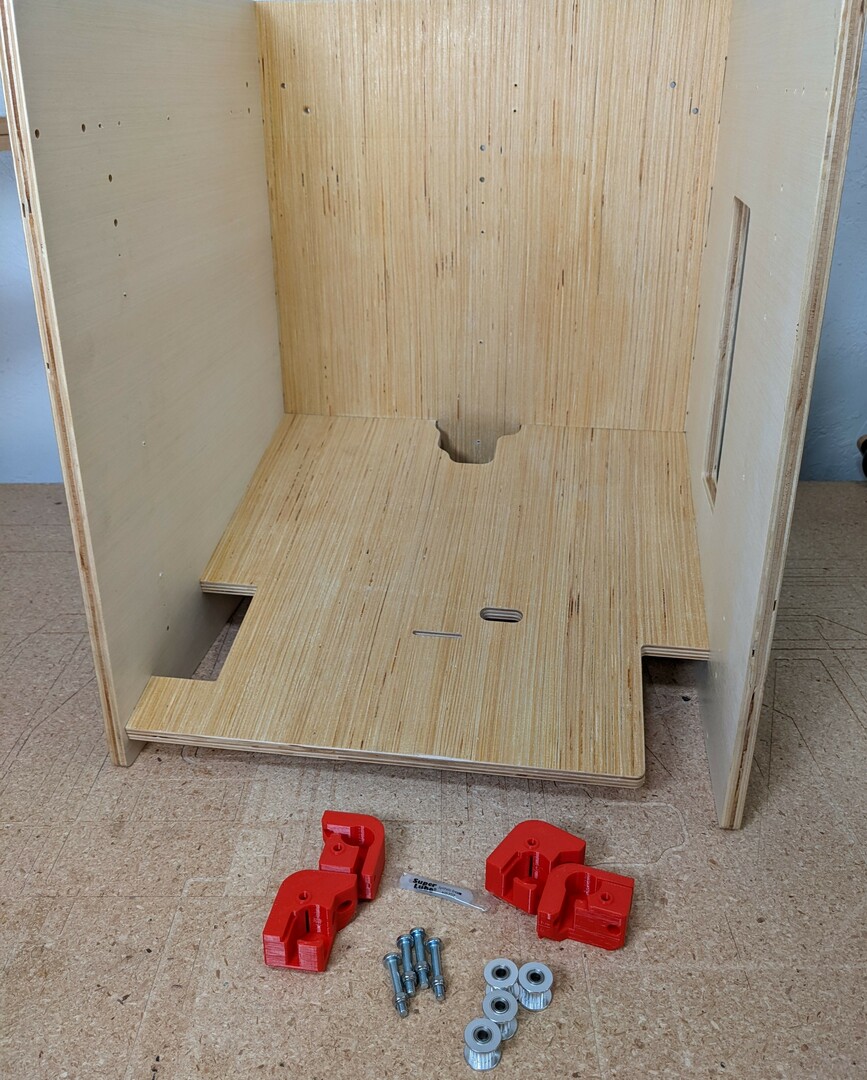
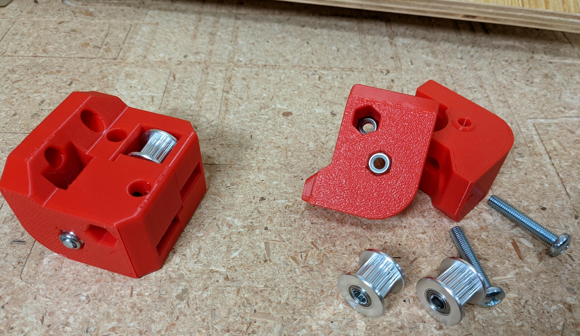
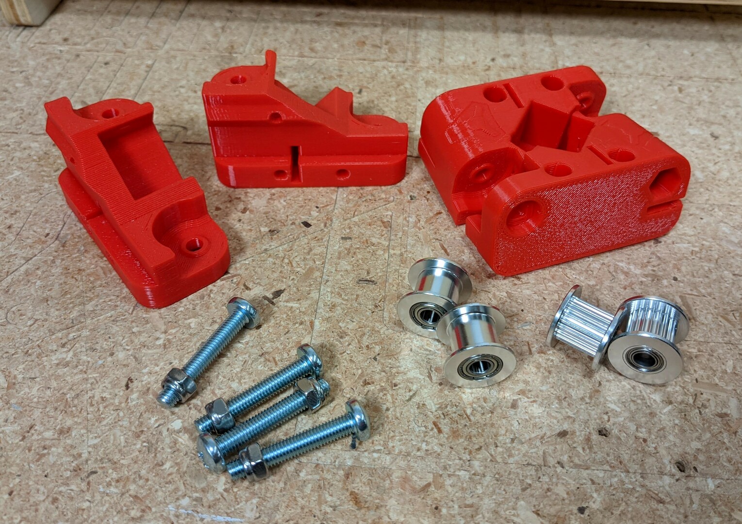
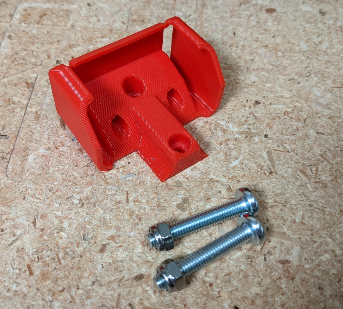
- Best to start by threading all the M5 nuts onto the screws to loosen up the lock nuts. Do this for all M5’s.
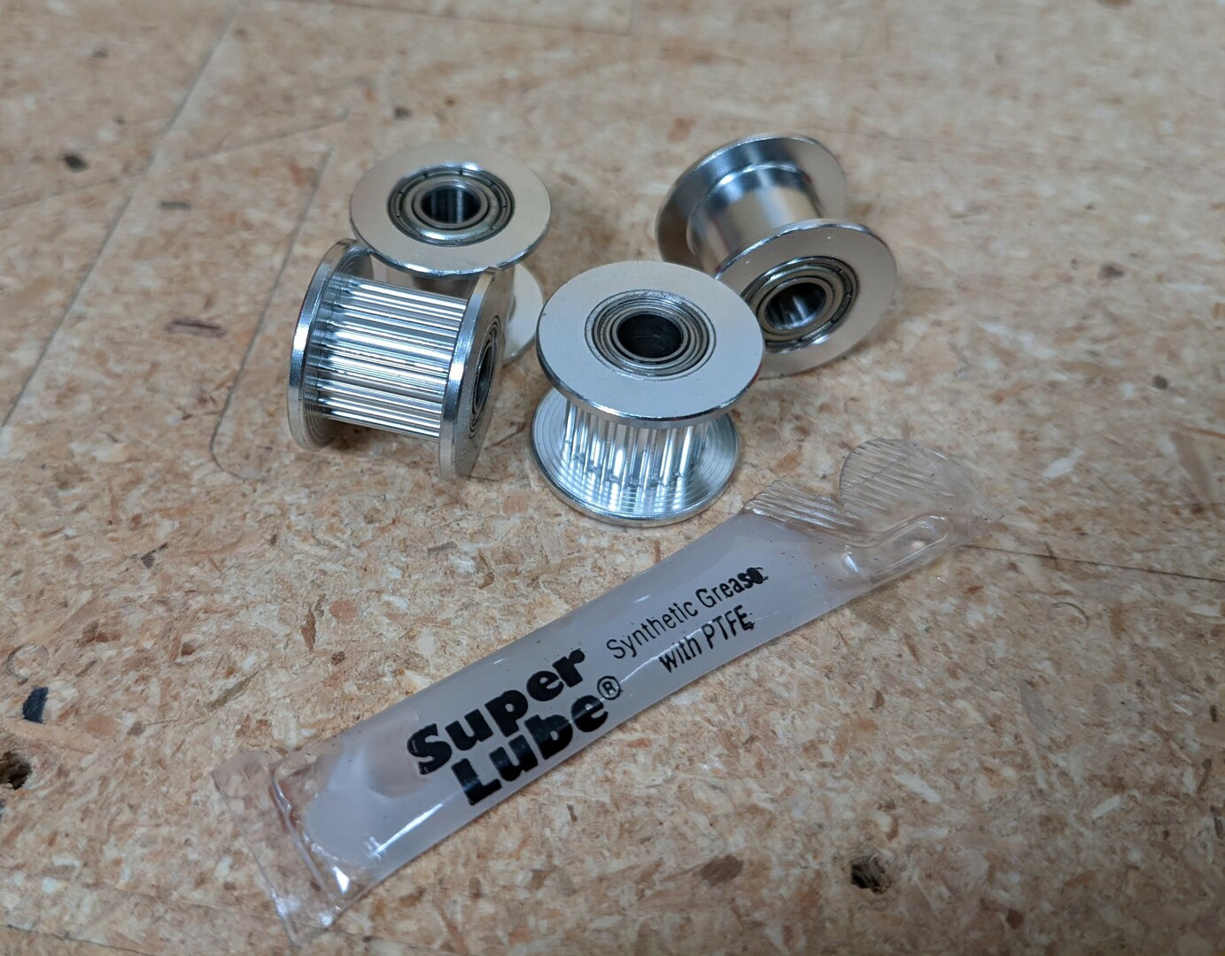
- Lube the Idlers (all idlers), Super lube is nice but others will work.
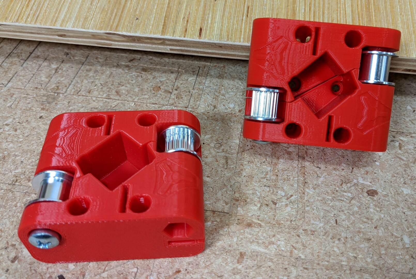
- Insert the nuts into the corner parts.
- Assemble with the idlers.
- Tighten the screws enough to assure the nuts are seated, then back off.
- Make sure the idlers still have free play on the screws.
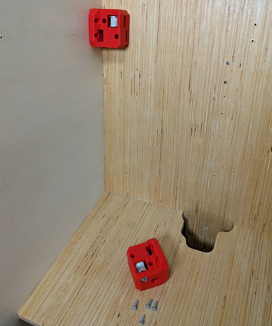
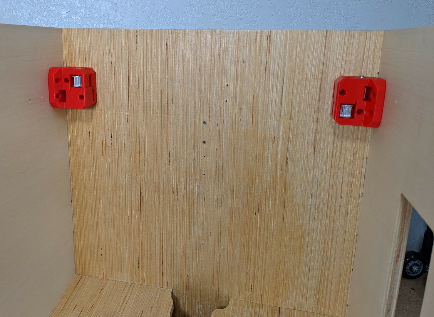
- Mount the corners with your frame screws. Snug.
- This picture is using press fit inserts so machine screws are used.
- Make sure the frame is still square.
Hub
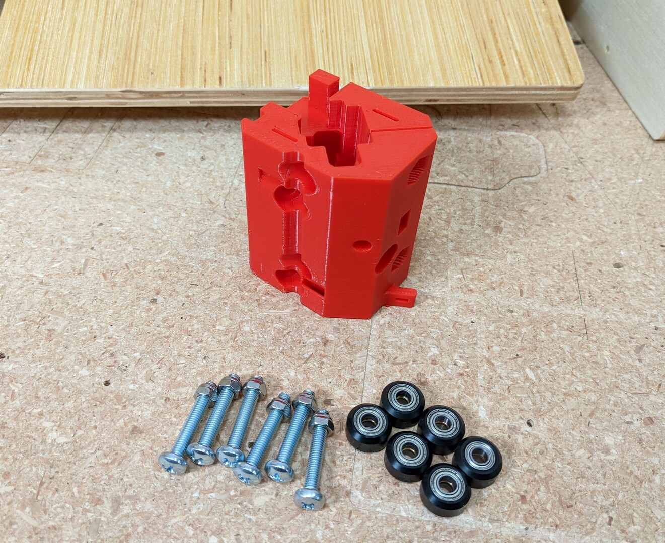
- Optional, lube the V-Wheels.
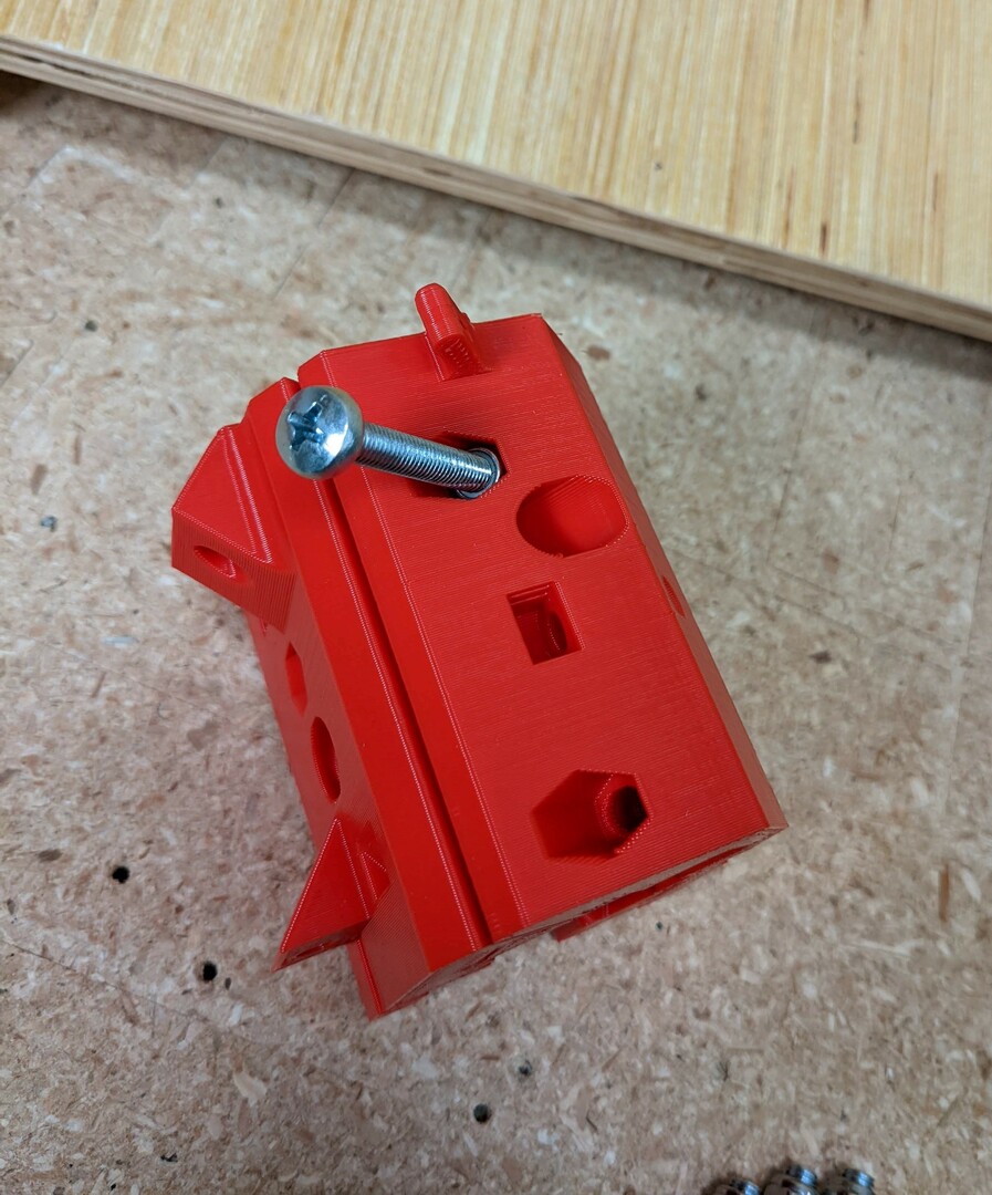
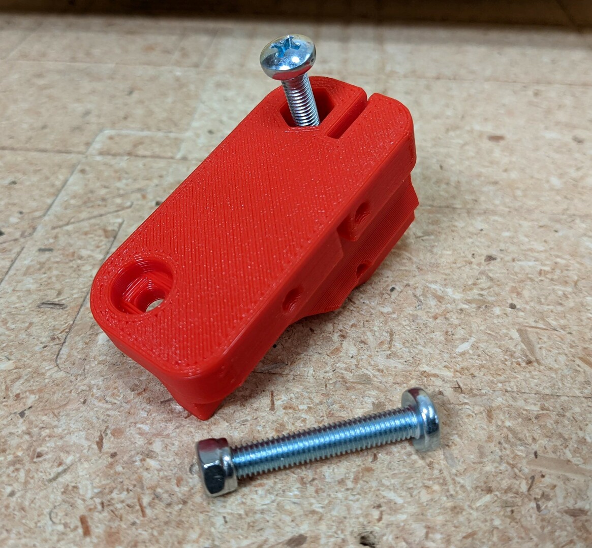
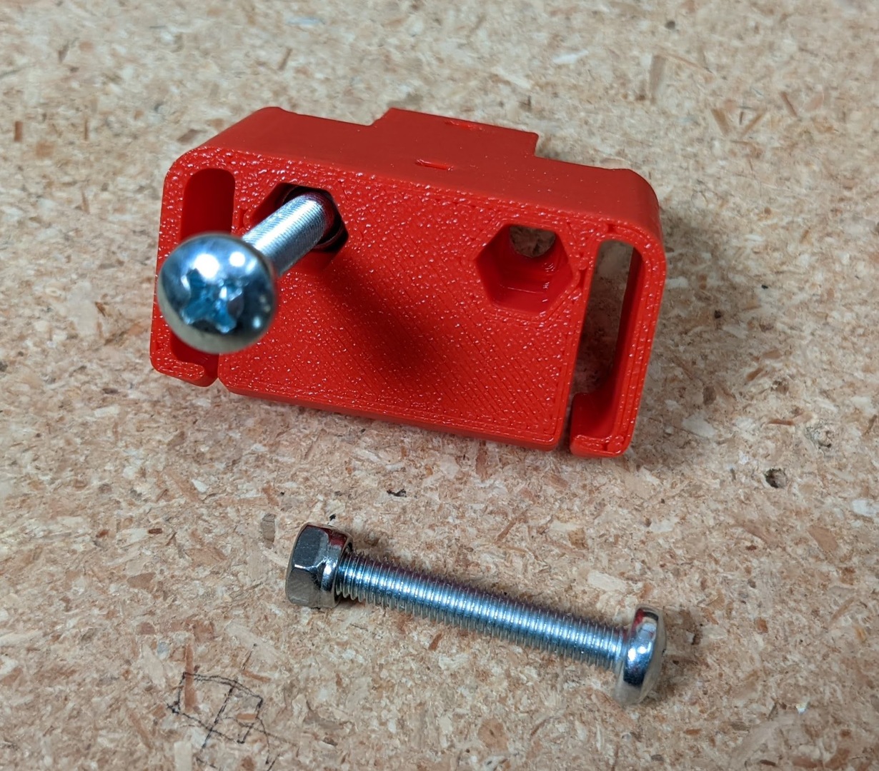
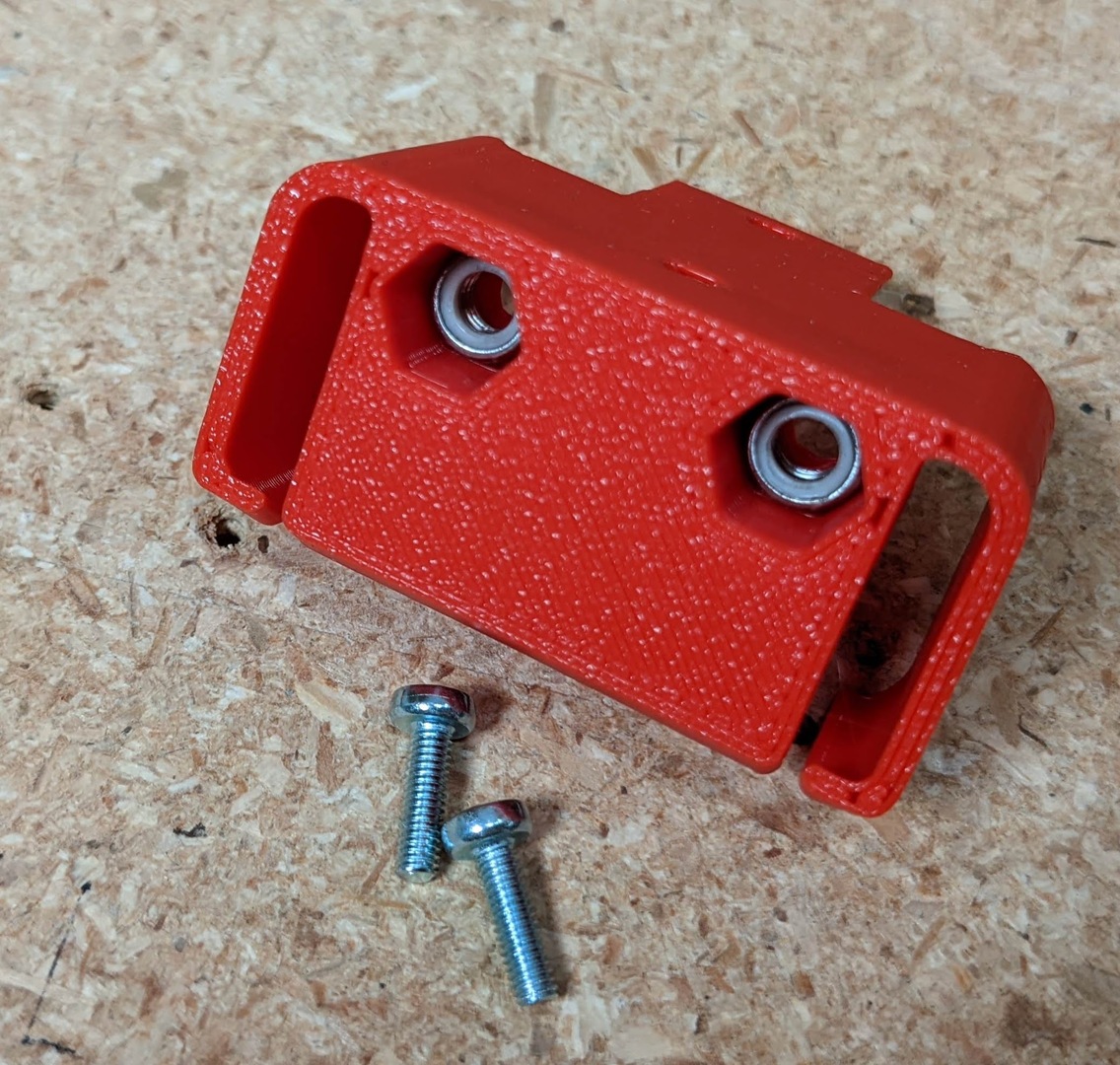
- A trick for inserting the nuts is to thread them on backwards and tap them into place.
- Tighten all the screws to assure the nuts are seated and back off.
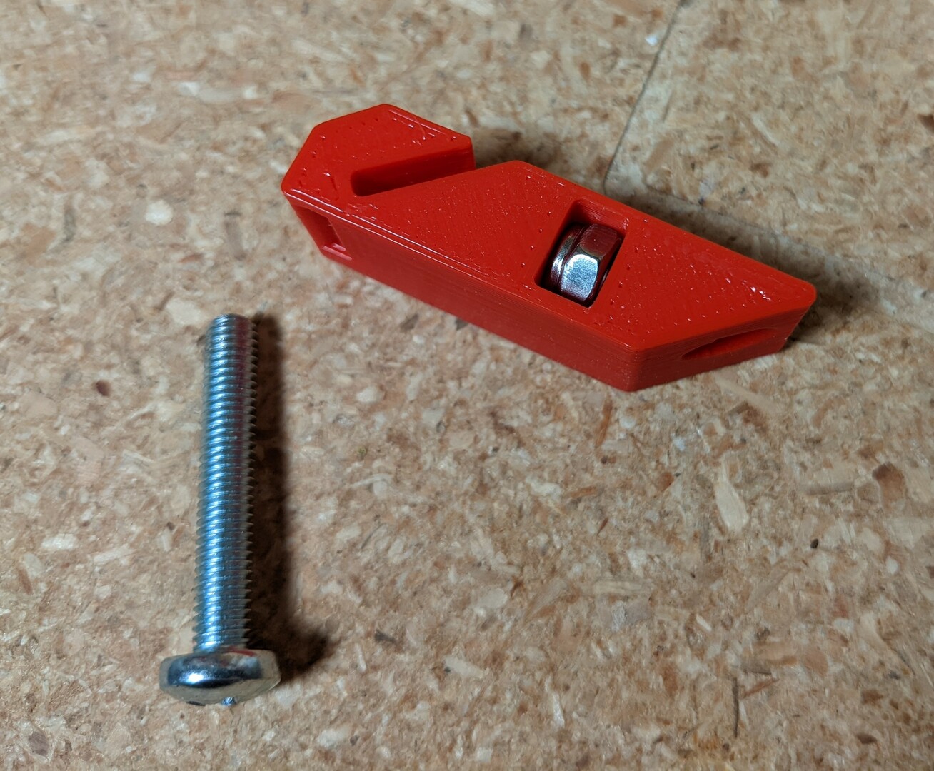
- The screw that jumps the gap controls tension - only thread this until it just hits the nyloc.
- You will adjust the tension just before printing.
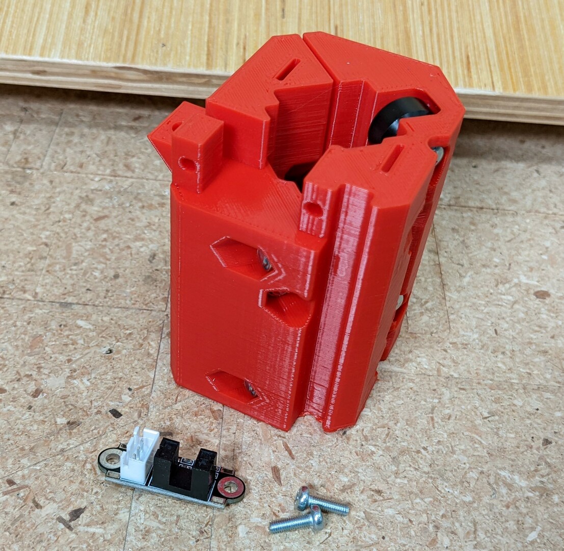
- These enstops must match this style or the triggers will not line up.
- M3x10mm screws.
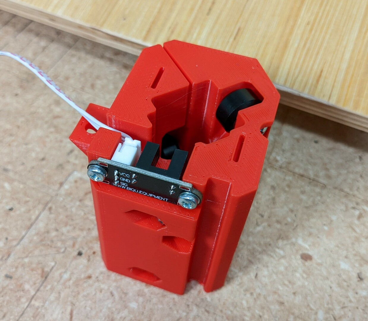
- Add the Endstop, in the orientation shown,
- Lightly snug the screws, do not strip the plastic.
- If you do strip the holes, loctite or superglue works to fix them.
Rail
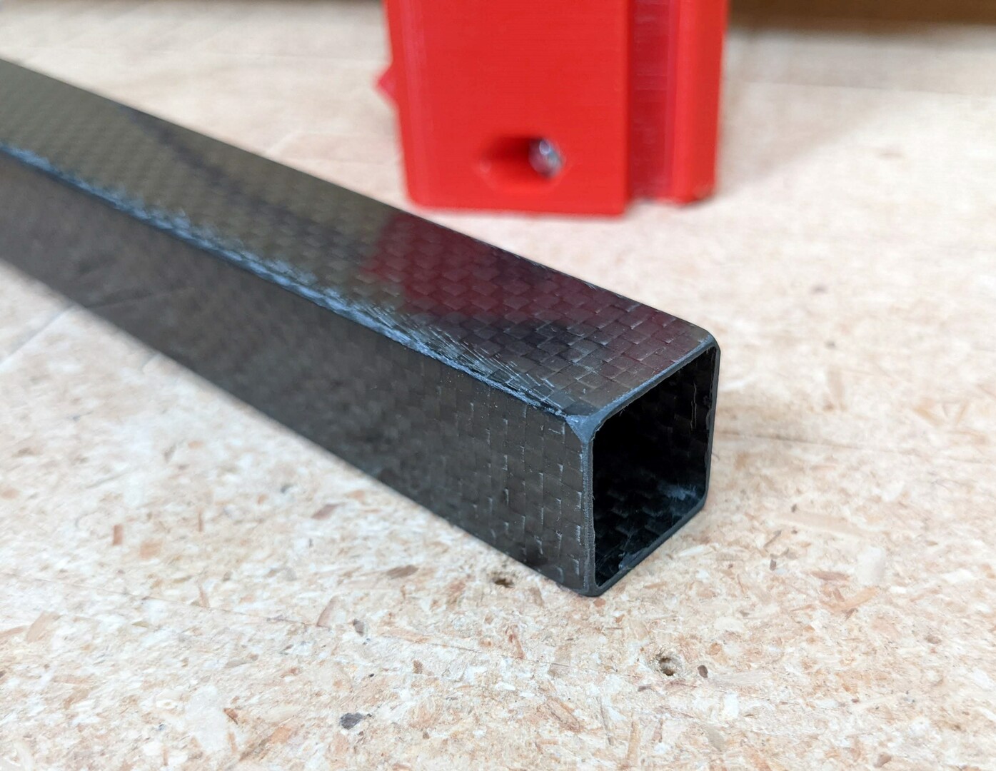
- Cut the rail to the length required in your CAD version. Aluminum or Carbon Fiber.
- Cut it a millimeter long and sand it to a precise length for easier assembly.
- Round the ends for ease of assembly.
- Avoid Carbon Fiber dust if using this as your rail.
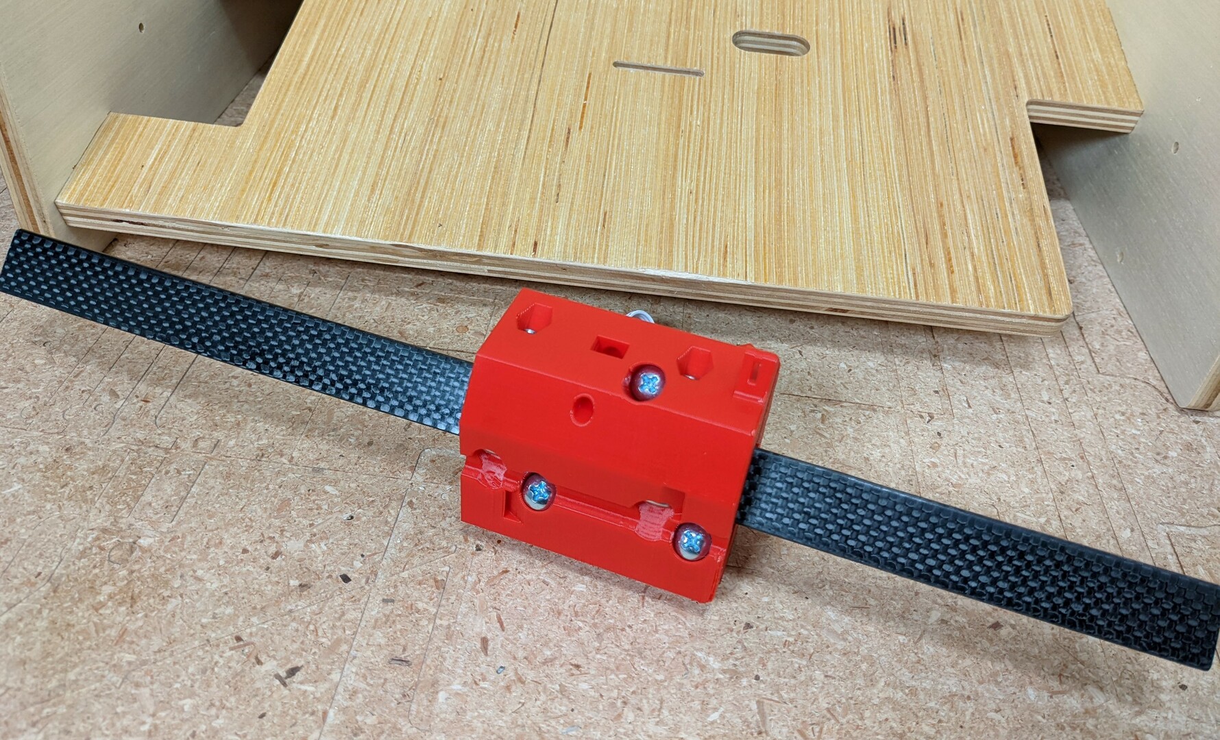
- Add the Hub, assure easy smooth rolling.
- Make sure it is not too tight as this can cause flat spots.
- You can rotate the tube 90 degrees to see if one way fits better.
Trucks
- Make sure the M5’s are pre-threaded.
- Nut trick for ease of assembly.
- Lube the idlers.
- Notice the position of the smooth idlers, they will face the steppers. One high one low.
- Very loosely assemble the trucks. They will be used for clamping in a later step.
Truck Triggers
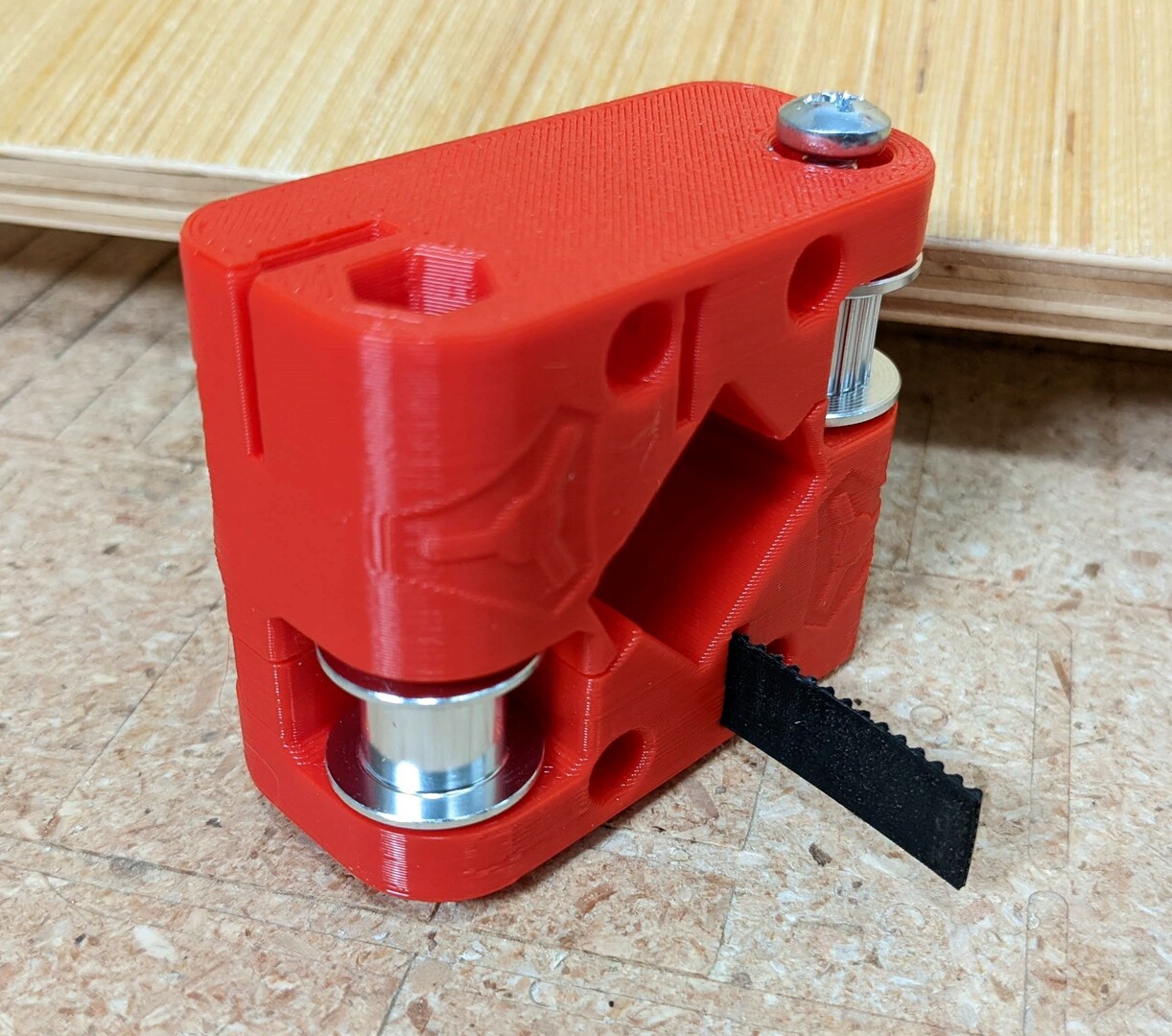
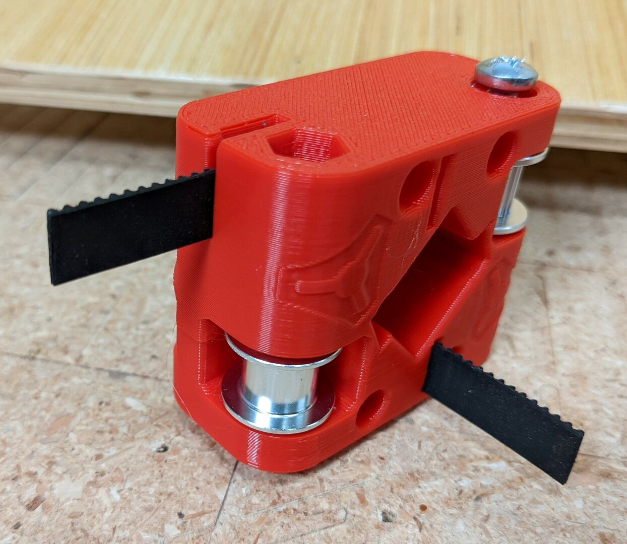
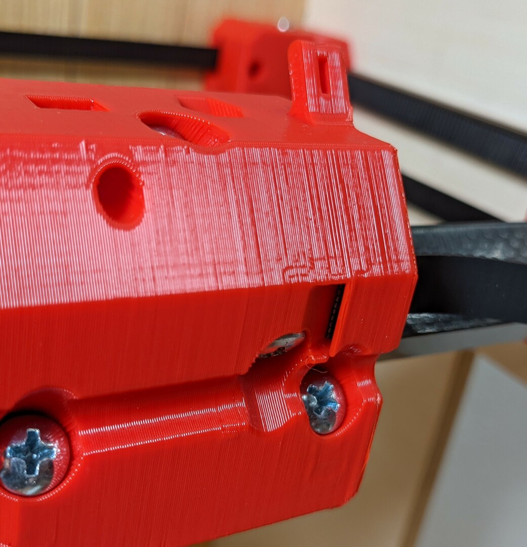
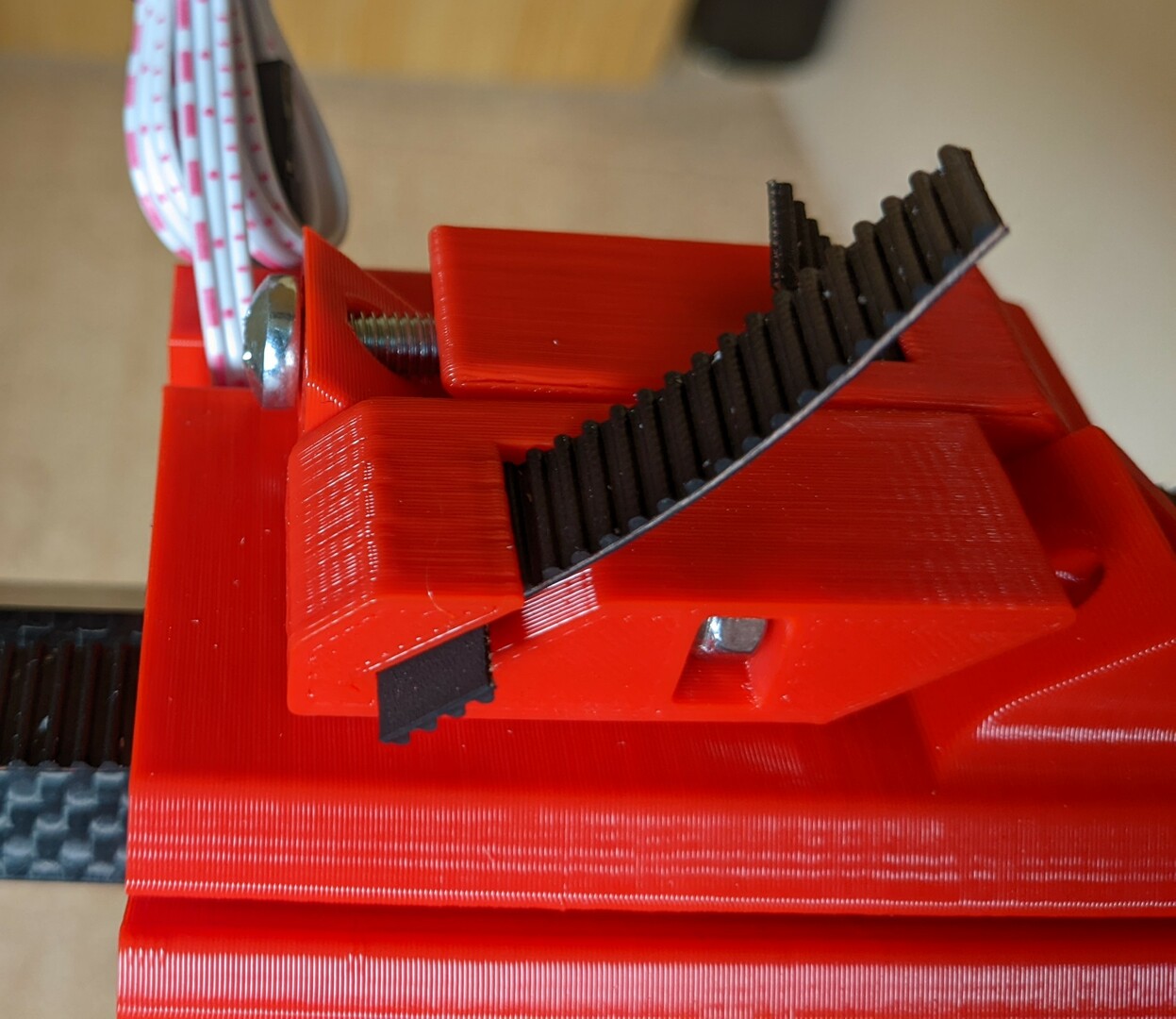
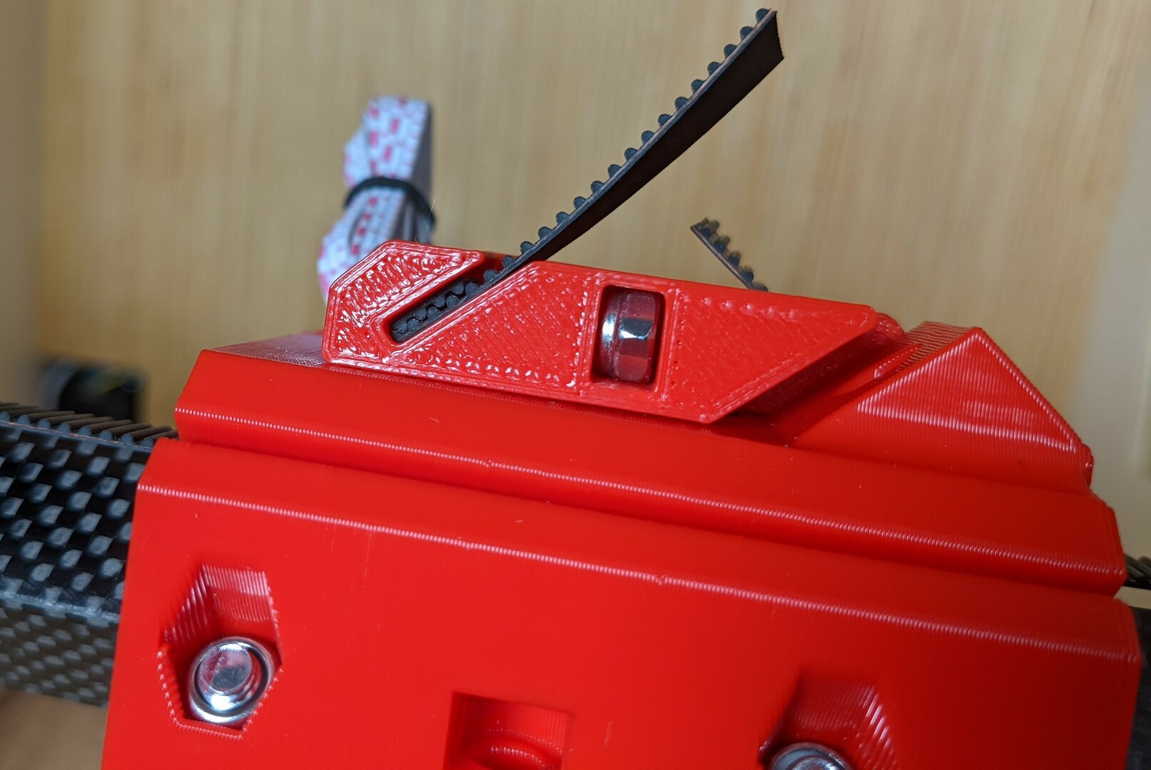
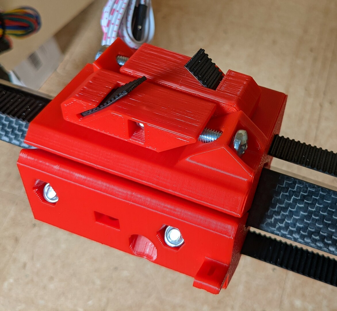
- This truck will get two triggers. The other truck has none.
- The trigger position relative to the smooth idler is important. This is the left / main truck.
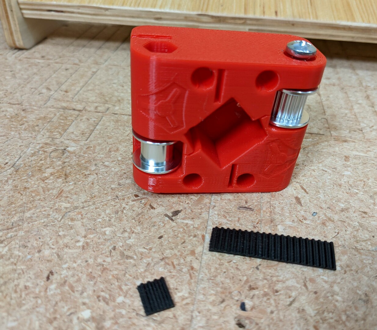
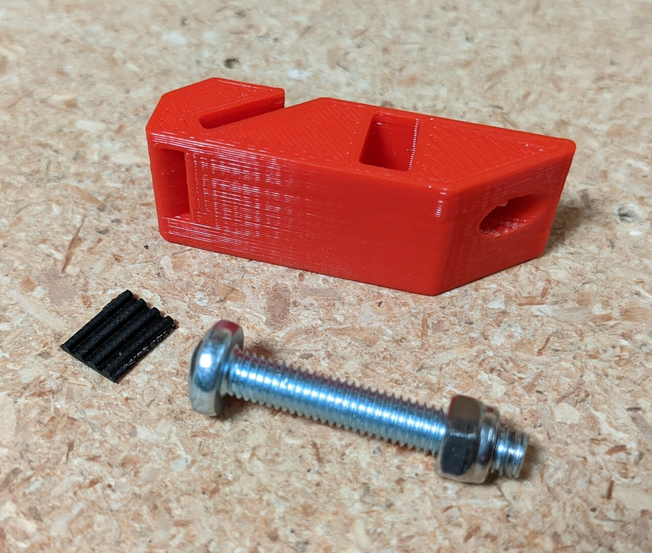
- A small locking piece 4 teeth long and a ~30mm piece is a good starting point for the lower trigger (X axis).
- See which way the teeth face.
- Insert from the back side, small locking piece at the end.
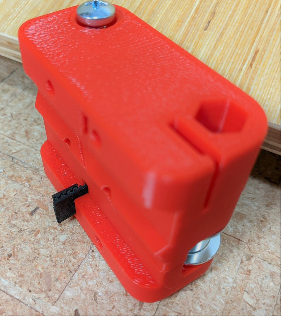
- Pull the belt through and make sure it is seated.
- Later you will trim this to fit.
- Add the Y axis trigger. This uses a 3 tooth locking piece. If your trigger is loose, use 3.5 teeth.
- Make sure it is fully inserted.
Core XY
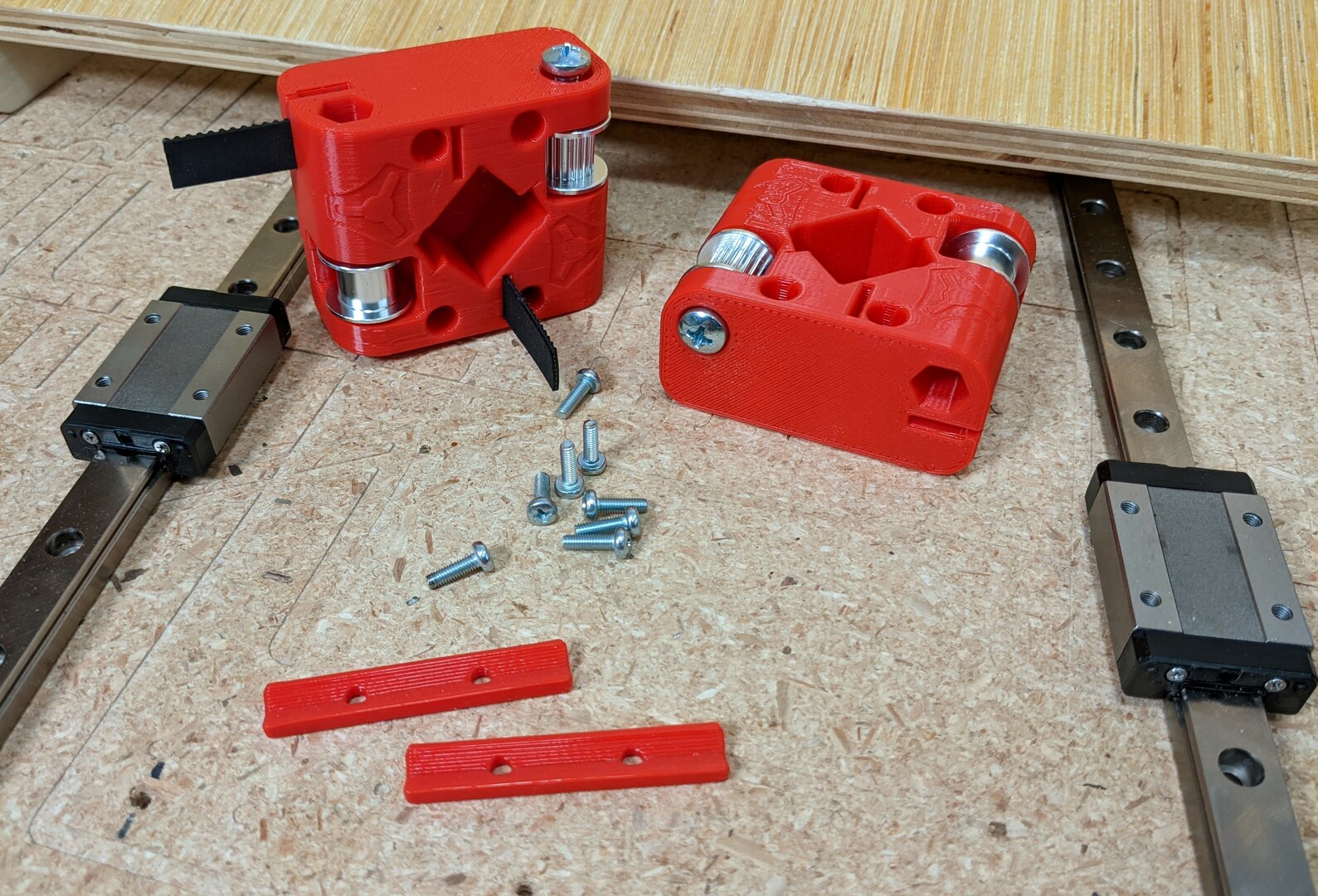
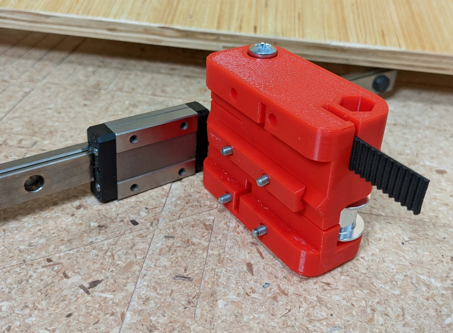
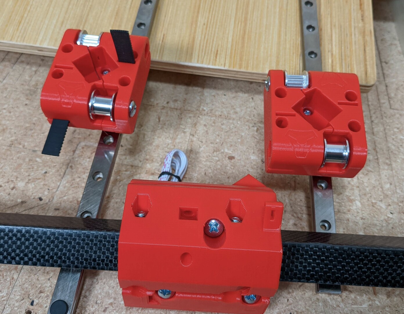
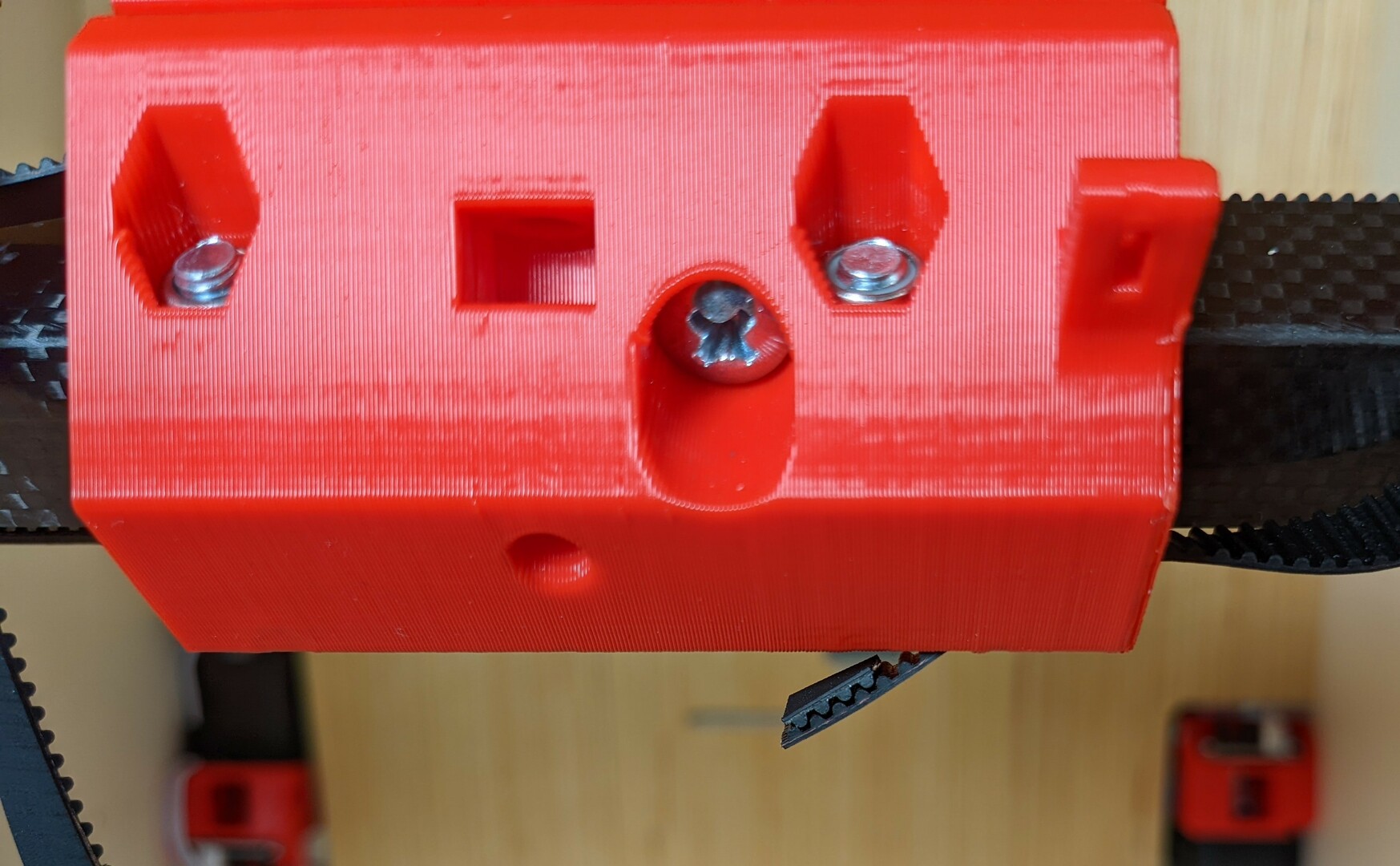
- Notice the small Truck Spacers, they go in the middle. (Shown in the next picture).
- Left / Main truck and right with M3x10mm screws.
- The left truck gets mounted high (middle and bottom screw positions).
- The right gets low (middle and high positions).
- The three screws on the same part get snugged up, the 4th screw gets lightly seated to allow for some movement if needed.
- Try to make sure the 3 screw half is mounted squarely.
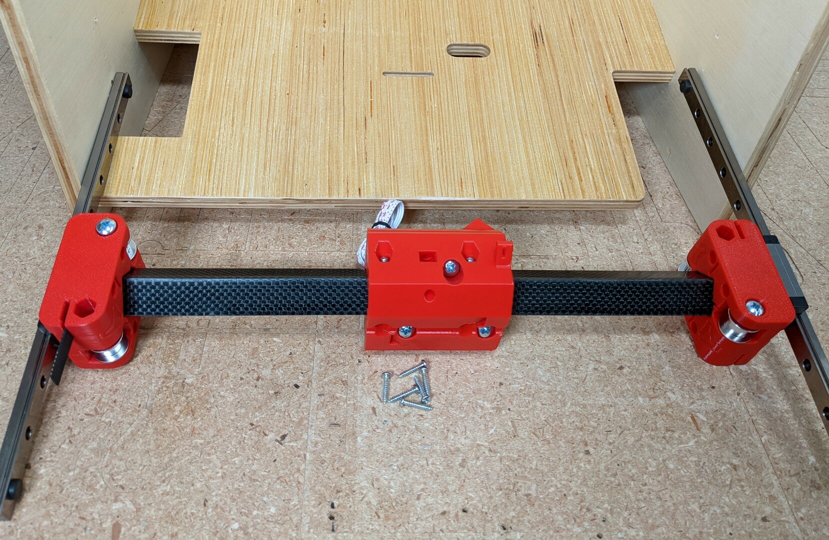
- Compare the truck and idler positions, as well as the Hub direction.
- Press fit the pieces.
- Slide the assembly into your frame and secure the rails with your frame screws.
- Check to make sure the rails are as parallel as possible.
- You can measure from the rail to the top of the frame, 20mm difference between sides.
- You can now lightly seat the truck M5 screws on the rail, ensure the Gap is equal front and back.
- Lightly, too tight and you can actually crack the rail.
Note
You can actually twist the rail with the truck screws. Using a flat reference across the top of your build you can measure your extruder to assure it is not twisting on the rail. If it is adjust opposite screws to twist the rail. Example - Tighten the front screw on the left and back screw on the right and the extruder will now slightly move up from as it moves from left to right (if the rail was level initially).
Stepper Mounts
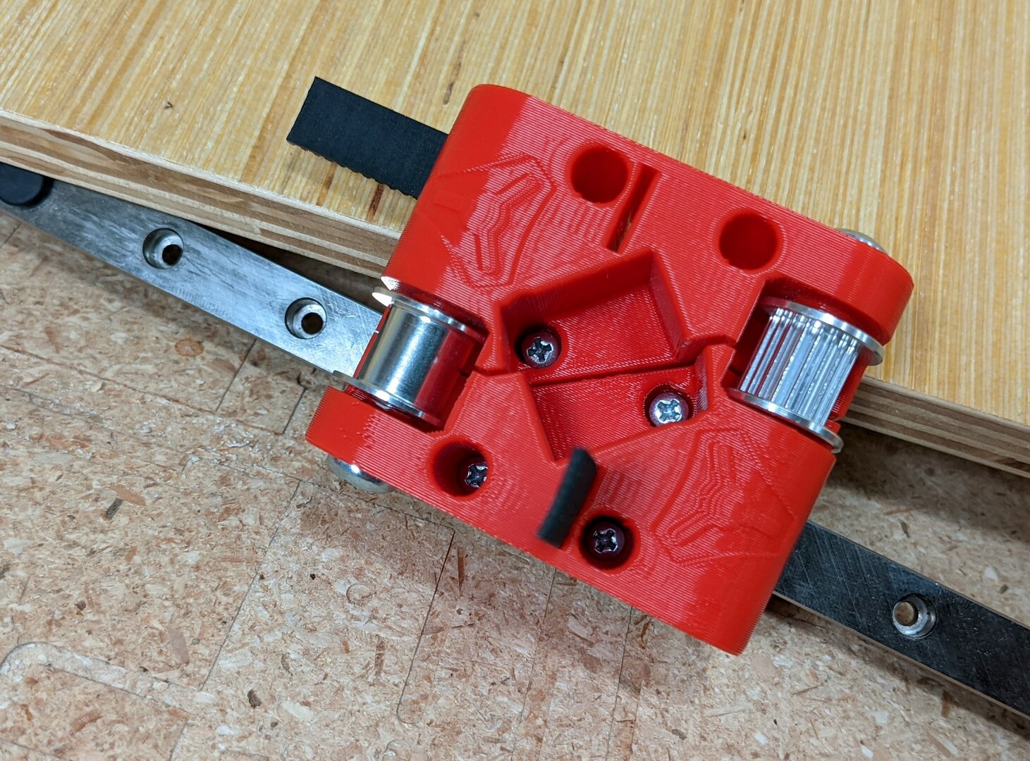
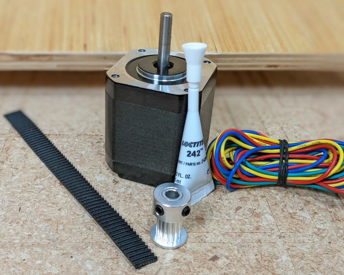
- Grub screws and loctite go hand in hand. Loose grub screws are the #1 issue in all the V1 builds.
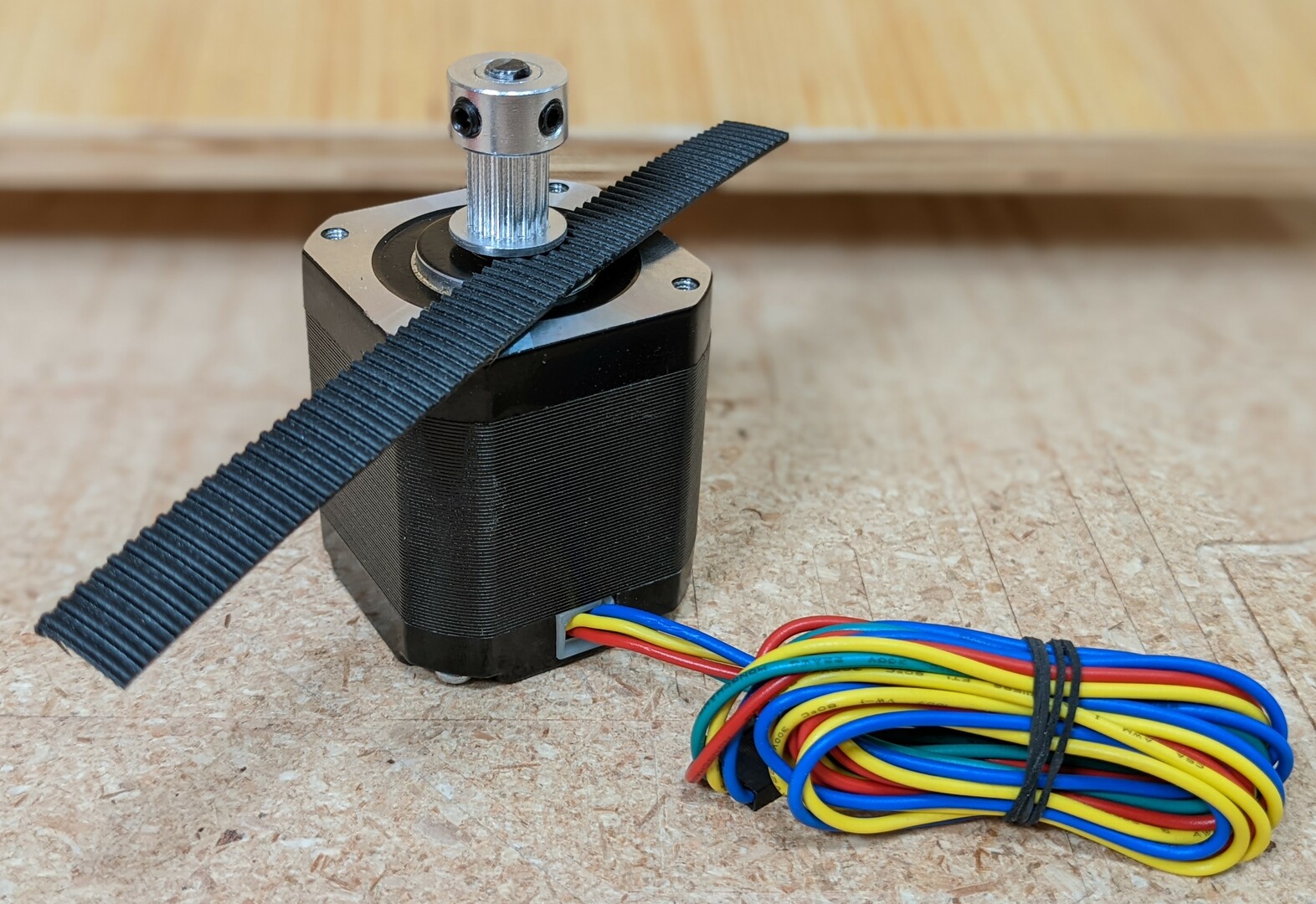
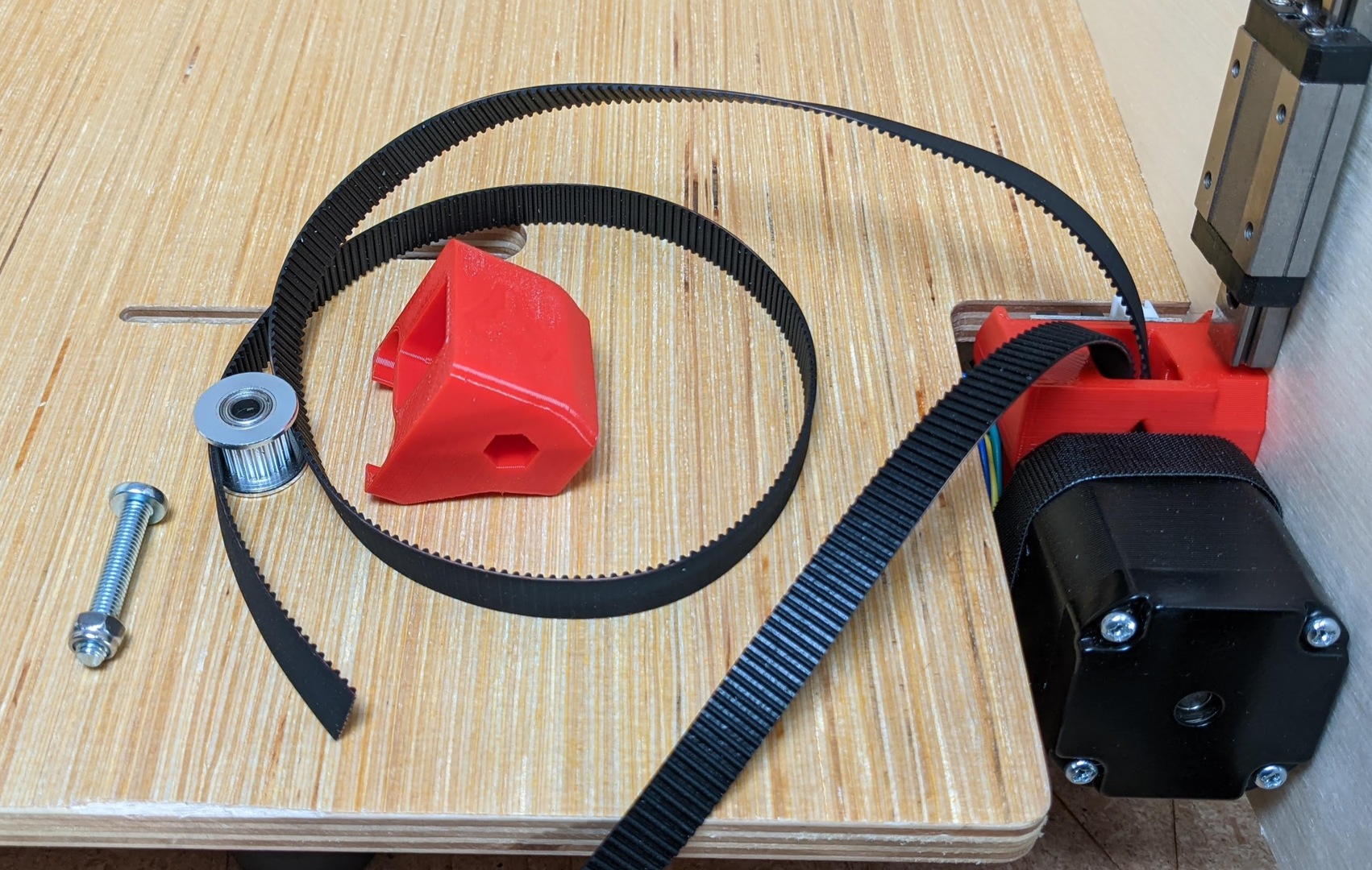
- Use a piece of belt as a spacer for the pulley.
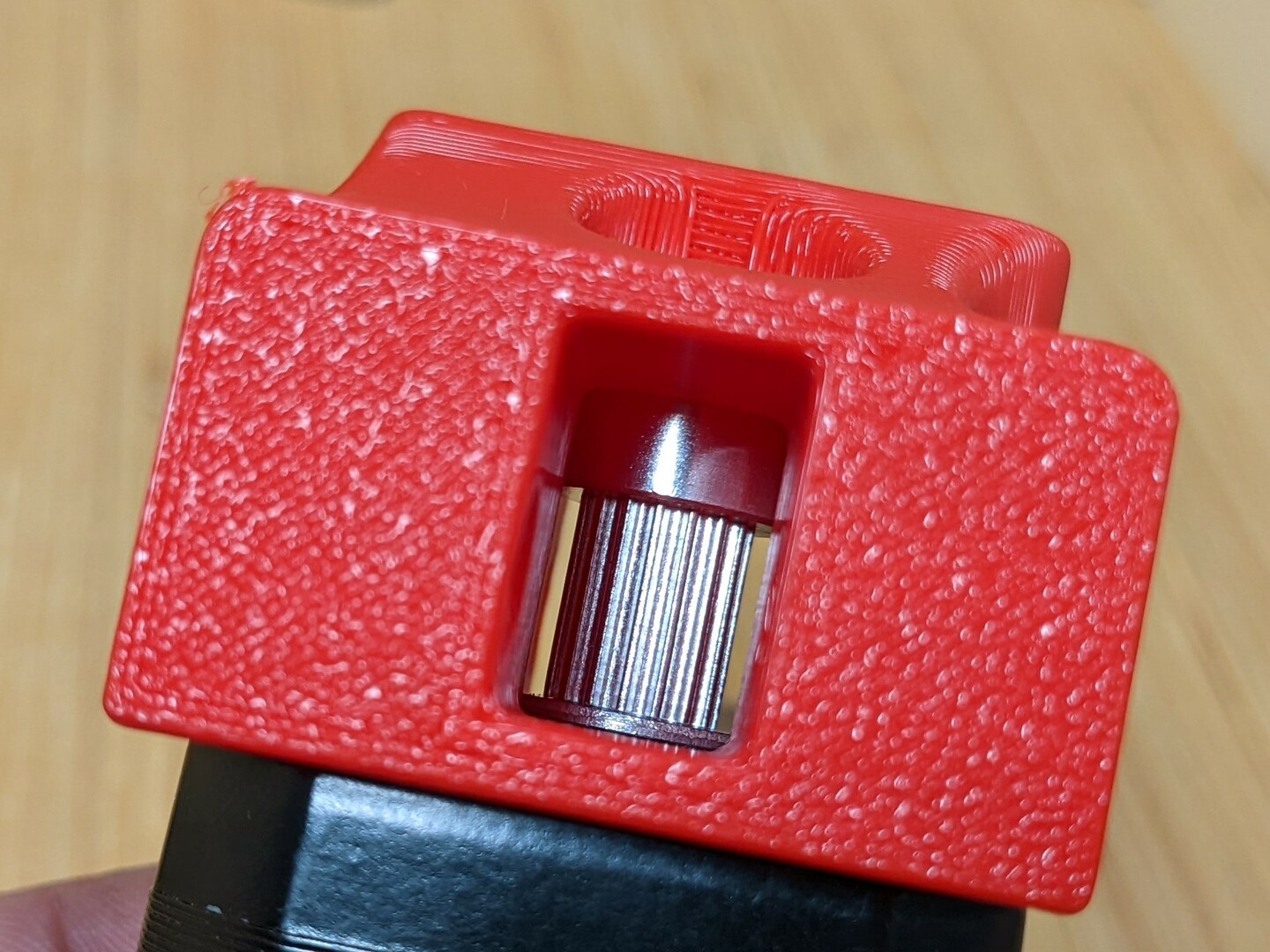
- Do a test fit to make sure the pulley is just a bit above the bottom surface as show.
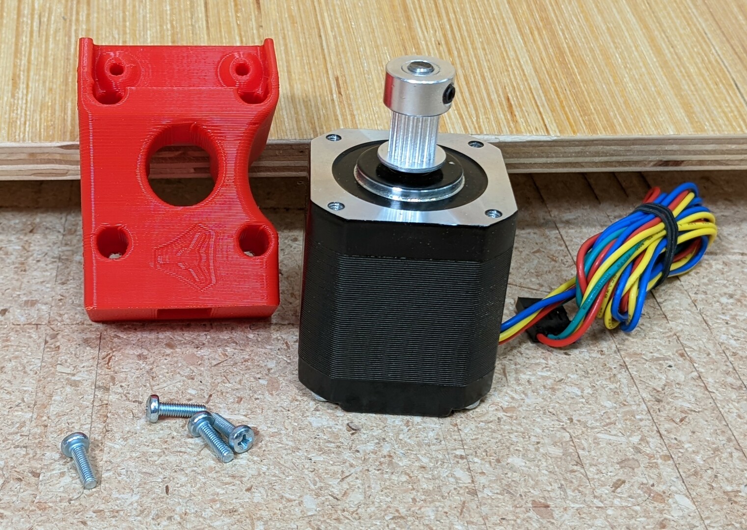
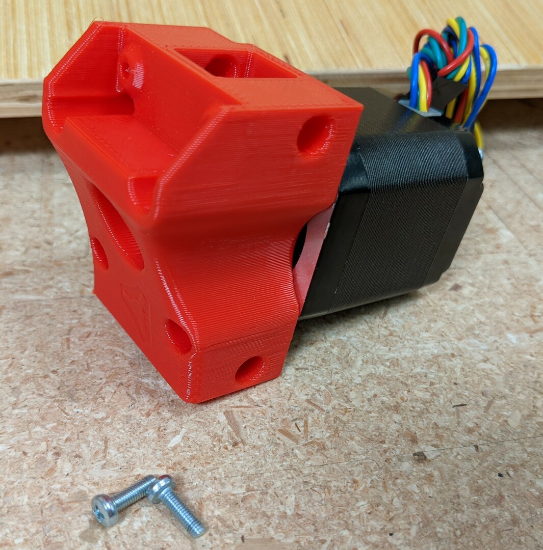
- Secure the steppers with M3x10 screws.
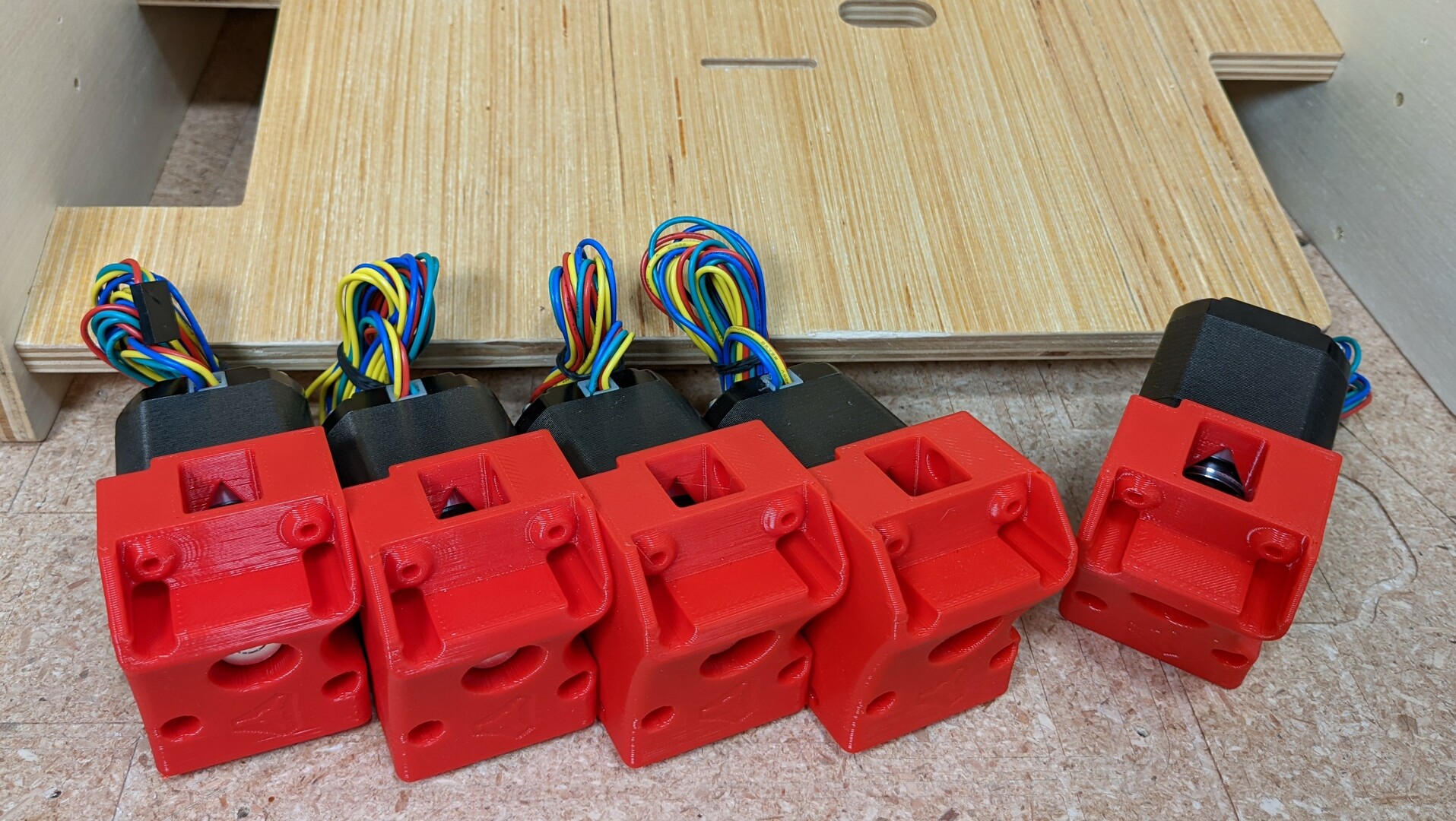
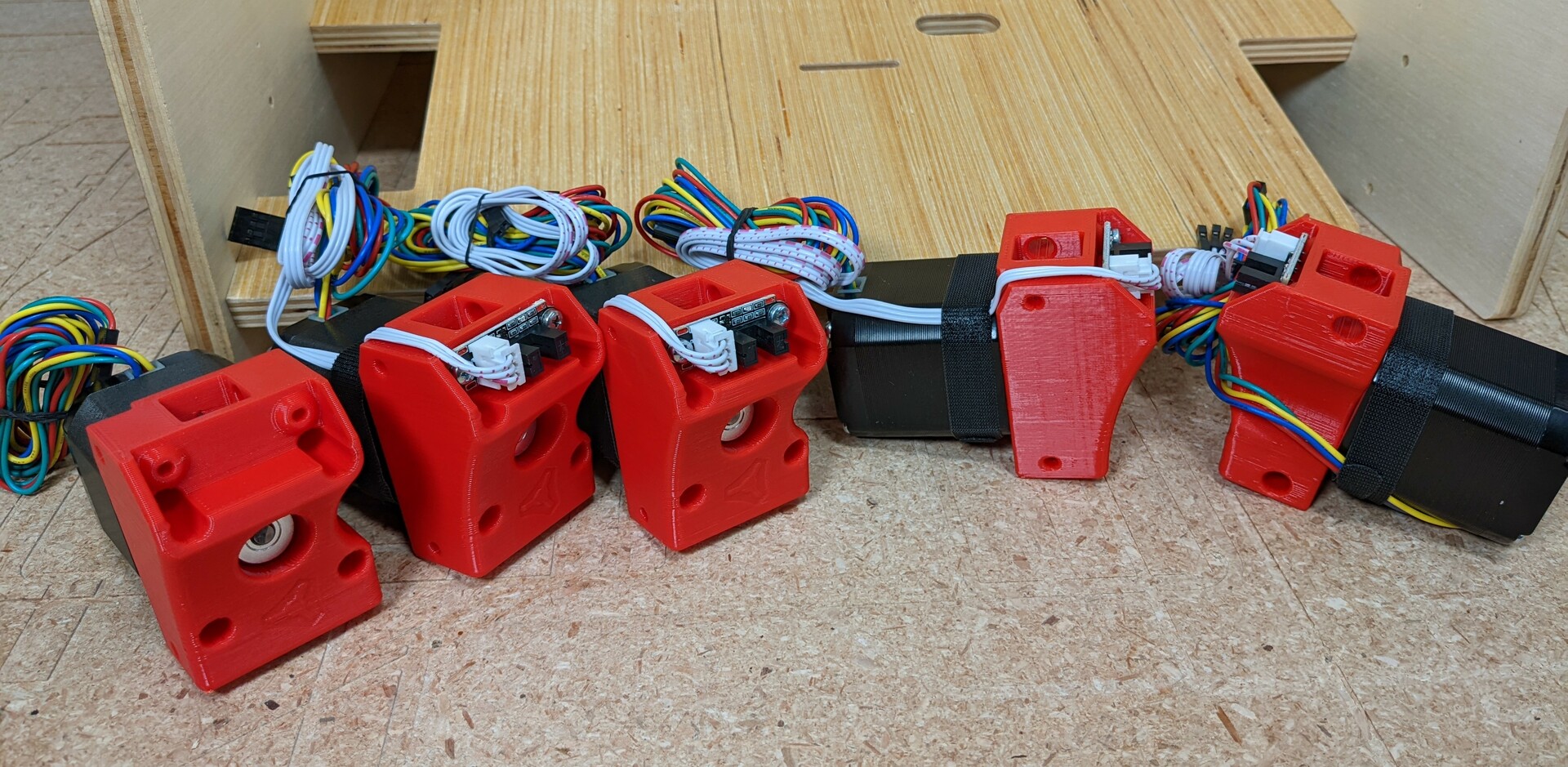
- I mount them with four of the wires facing up, one down.
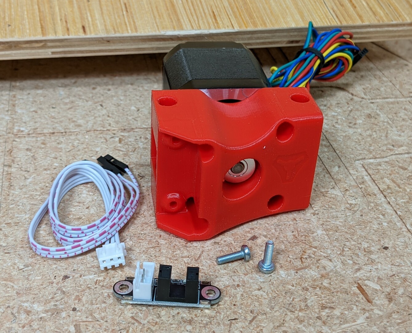
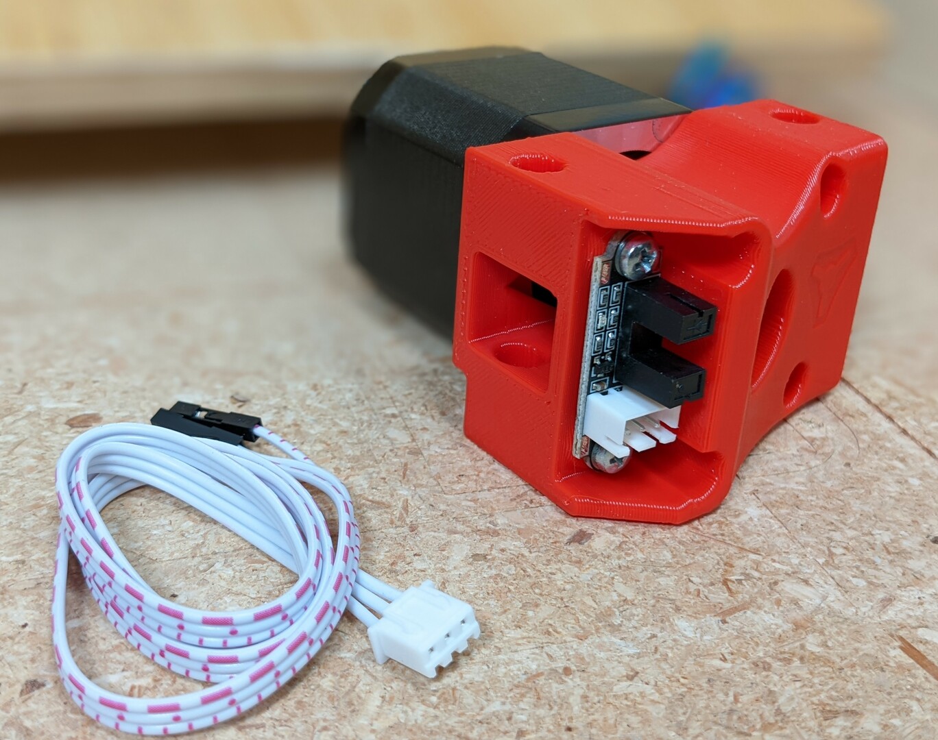
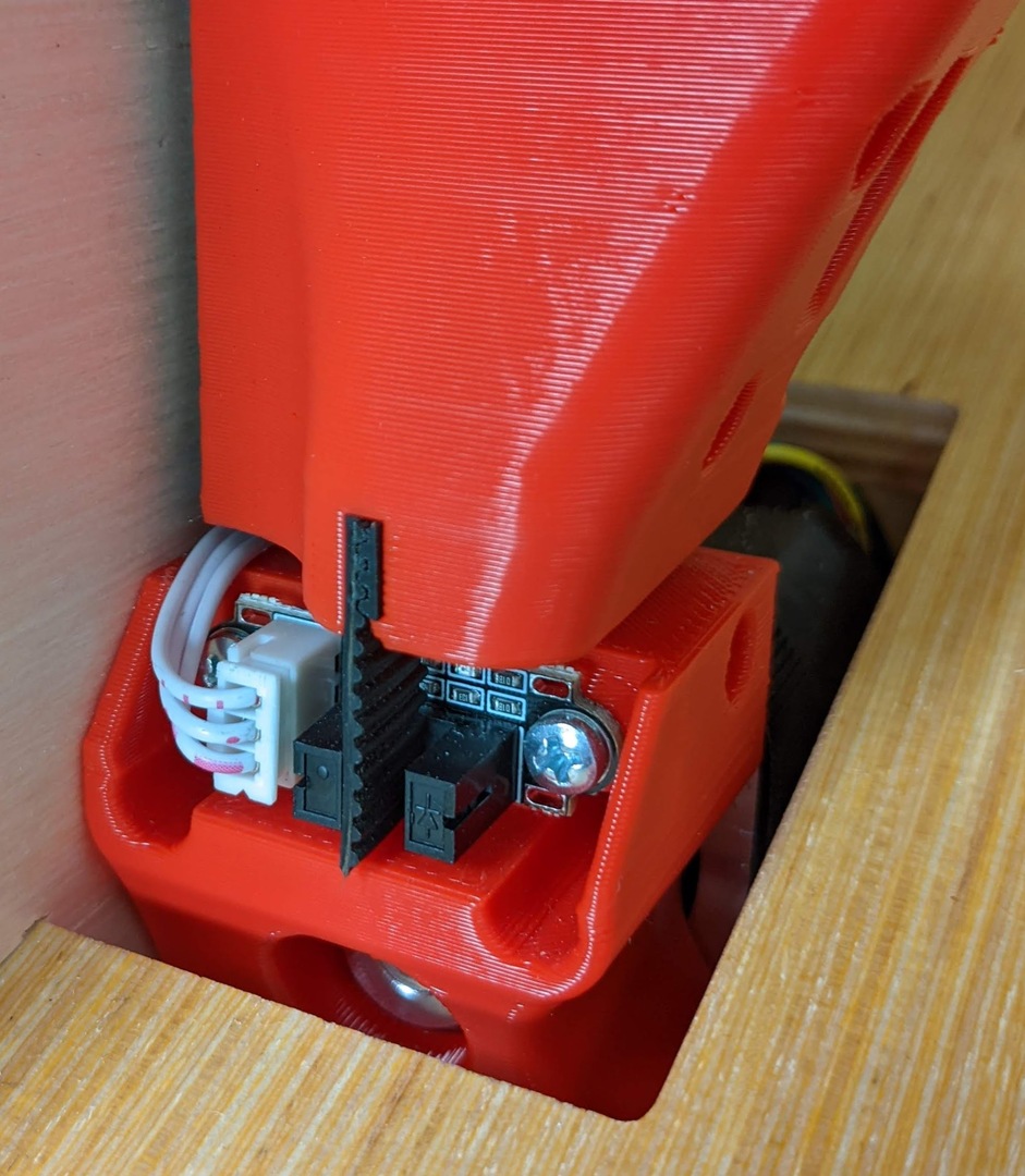
- Four get endstops.
- All four endstops are mounted in this orientation.
- I like to run and secure the wires as shown, for now.
- Mount the steppers with your frame screws.
- The mount with the wire down goes in Z2, the lower right stepper, shown in the next picture.
Belting the Gantry
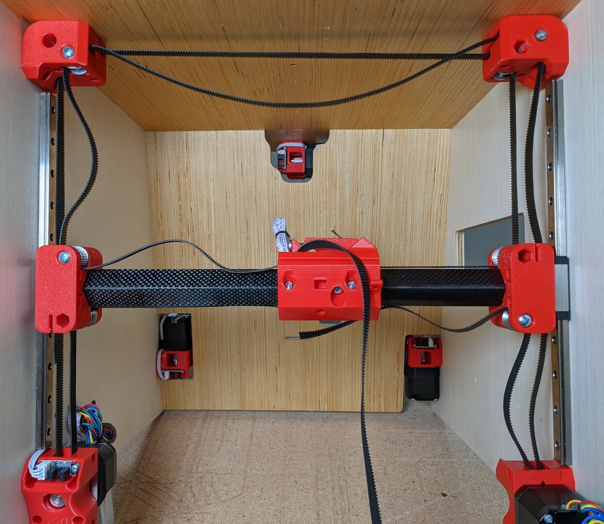
- This is the best picture I could come up with. Low belt shown tight, high belt shown loose.
- Feed the belt in from the hub and work your way around.
- No twists, no crossing.
- Cut the belt leaving 30mm or so on each end when pulled snug. You can trim it further later.
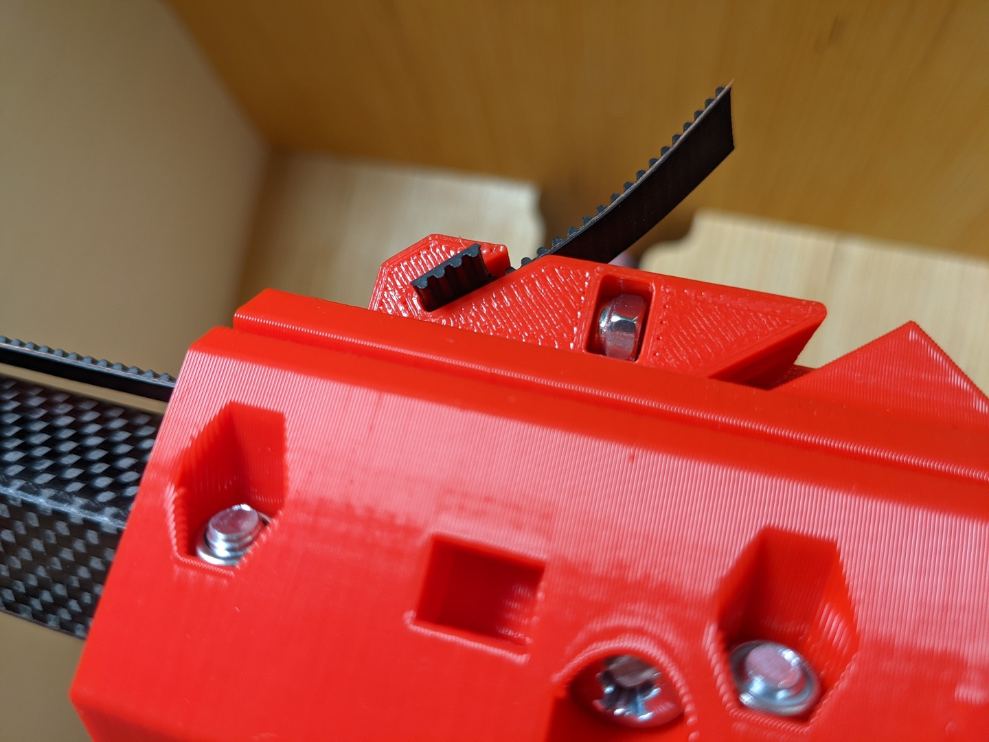
- lock the belt in the front with a 4 tooth segment.
- Pull it in and make sure it is at least flush if not a bit further in.
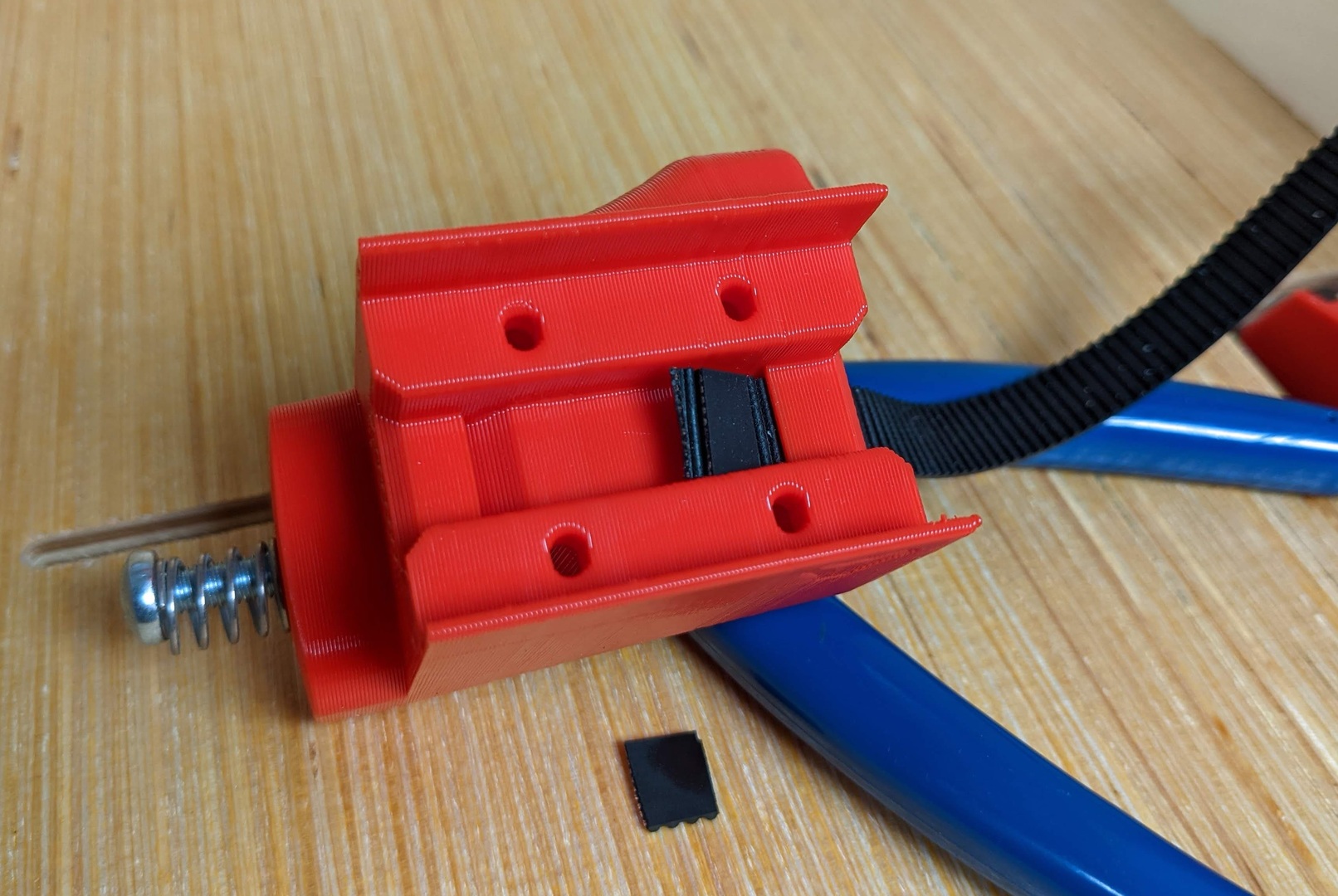
- The Belt Tugger gets locked with a 4 tooth segment.
- Seat the nut.
- Okay, this part is fiddly. It might take a few tries to get right.
- Feed the belt through and pull it snug. You can use pliers.
- The lock, when fully inserted, will loosen up 2mm. It sinks in a bit.
- Make sure the lock is fully seated.
- Trim the belts a bit, leave a little room in case you need to snug them up later.
- Insert the screw.
- Try to get both belts lightly tensioned and equal.
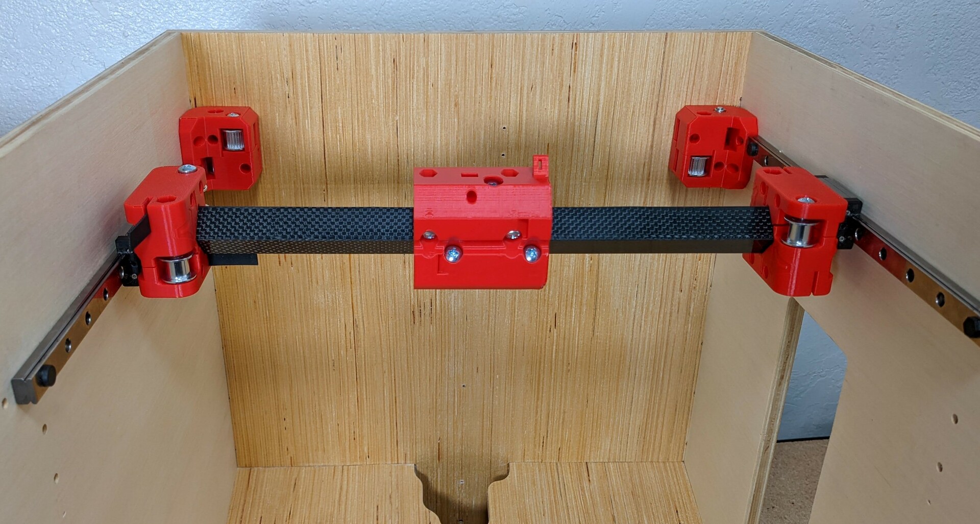
- Measure the coreXY diagonals from the back corners to the trucks to make sure it is square.
- Adjusting the belt tension will change the angle of the X axis rail. Give the belt a little tug to see which way the rails angles.
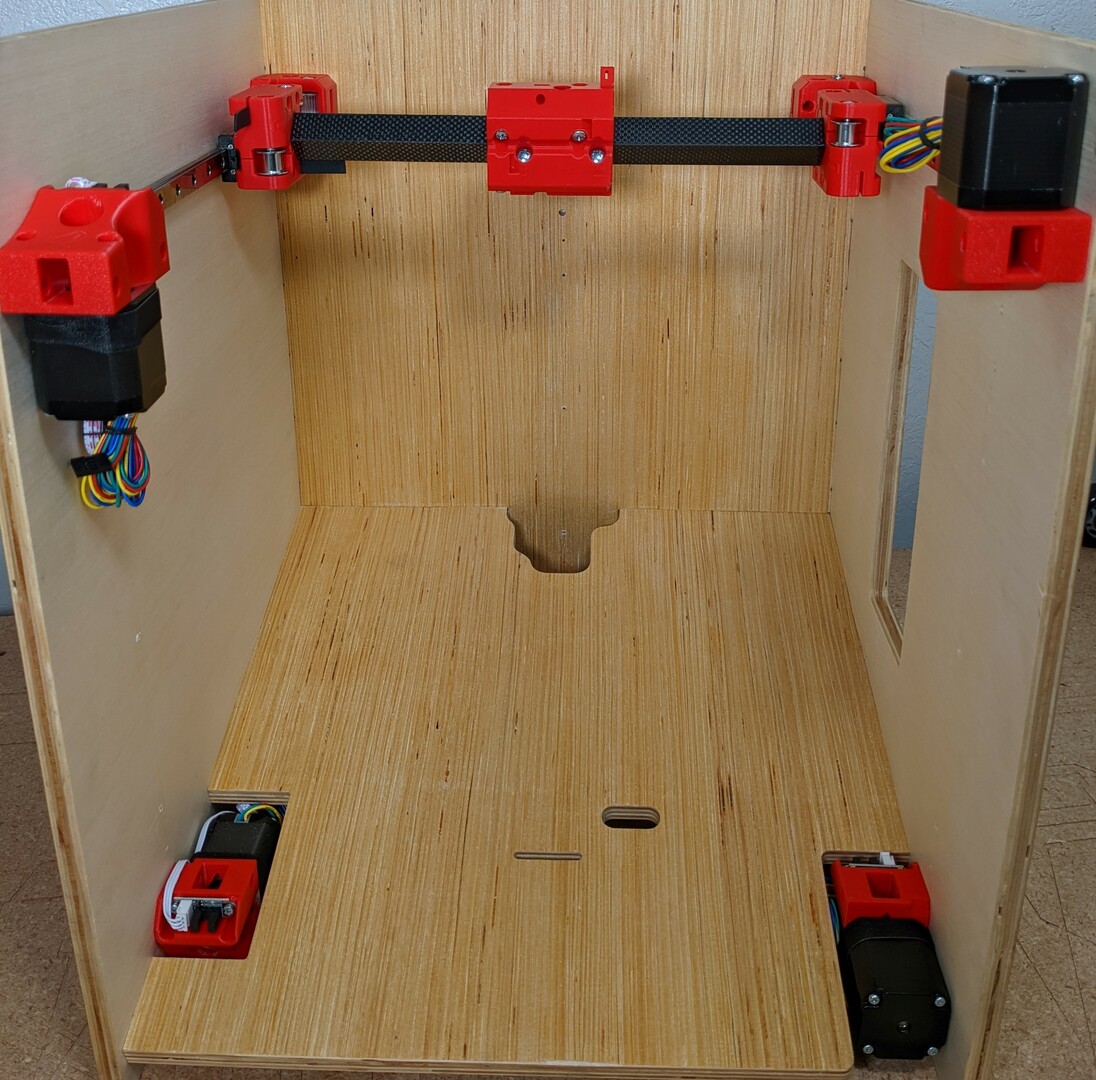
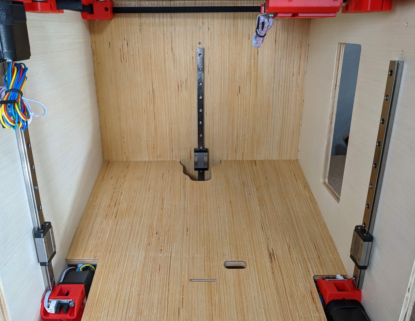
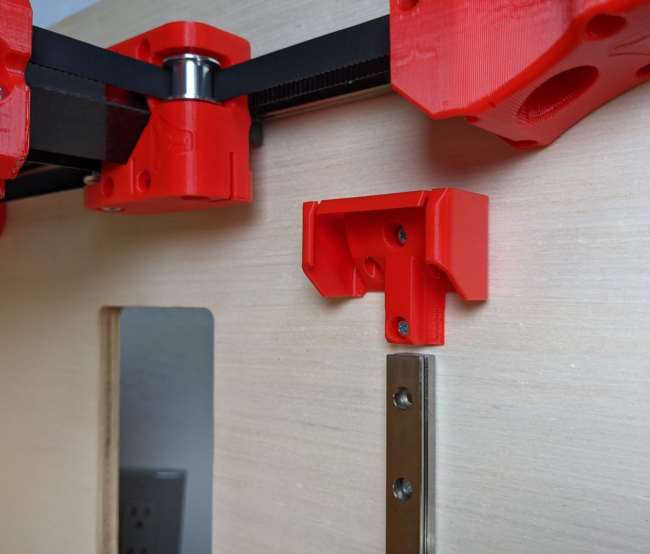
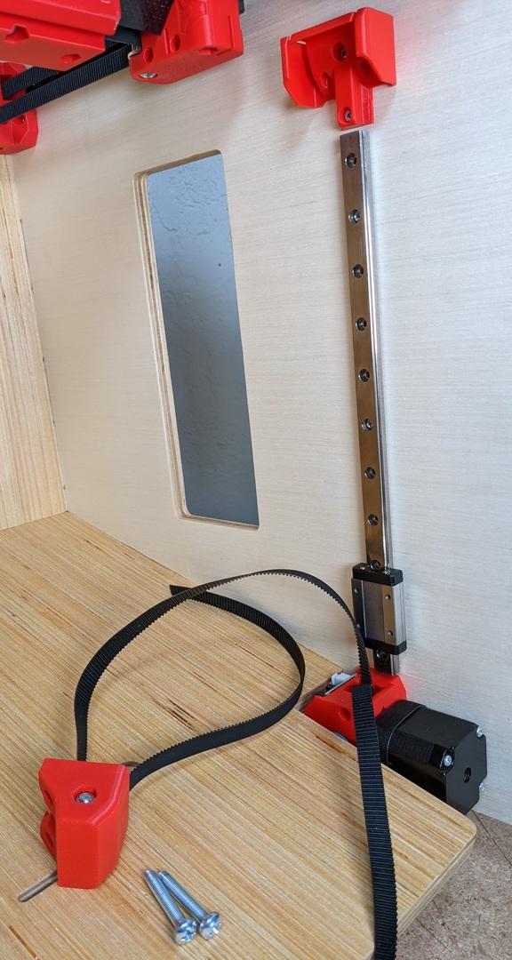
Z axis X3
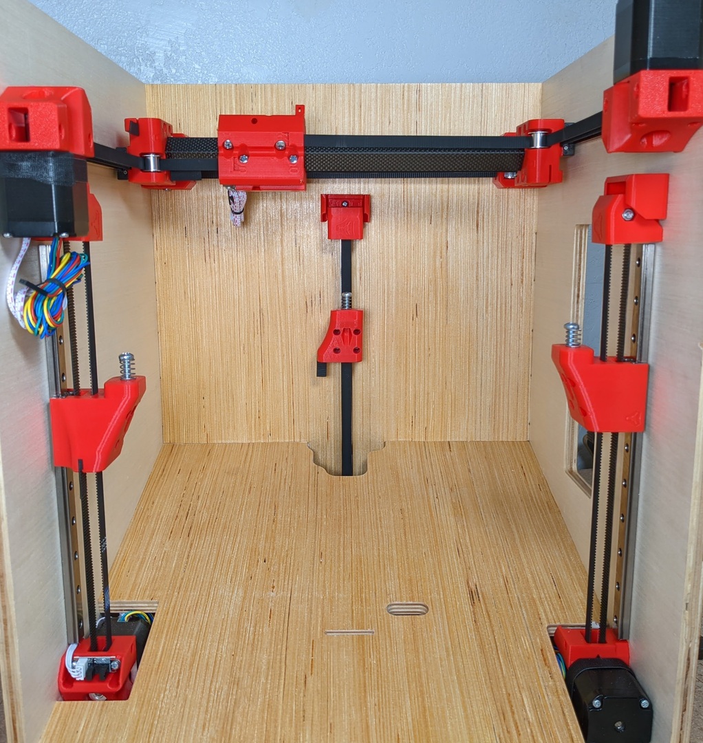
- Go ahead and mount all three rails. Take a few measurements as you can screw the them a bit if needed.
- Nice right!?
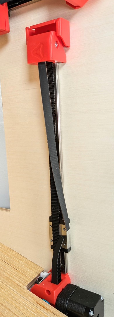
- I find it easiest to run the belt as I go, in the direction shown.
- Lube that idler.
- Assemble the idler into the Z idler part. Screw lightly seated.
- Assemble with the belt in place. This is the only belt that is hard to do after the fact (but it can be).
- Z Post.
- Seat the nuts.
- Mount the post with your frame screws.
- There should be a gap and the post should be square to the rail.
- Attach the Z idlers as loose as possible. At least to take a belt measurement later.
Note
It can be easier to take these off when setting or adjusting the belt tension on this axis.
- Cut the belt just short of touching the other end.
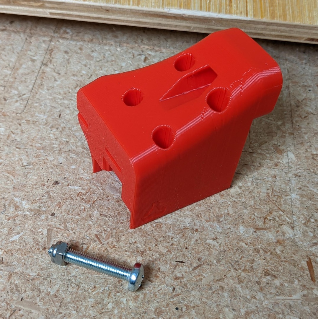
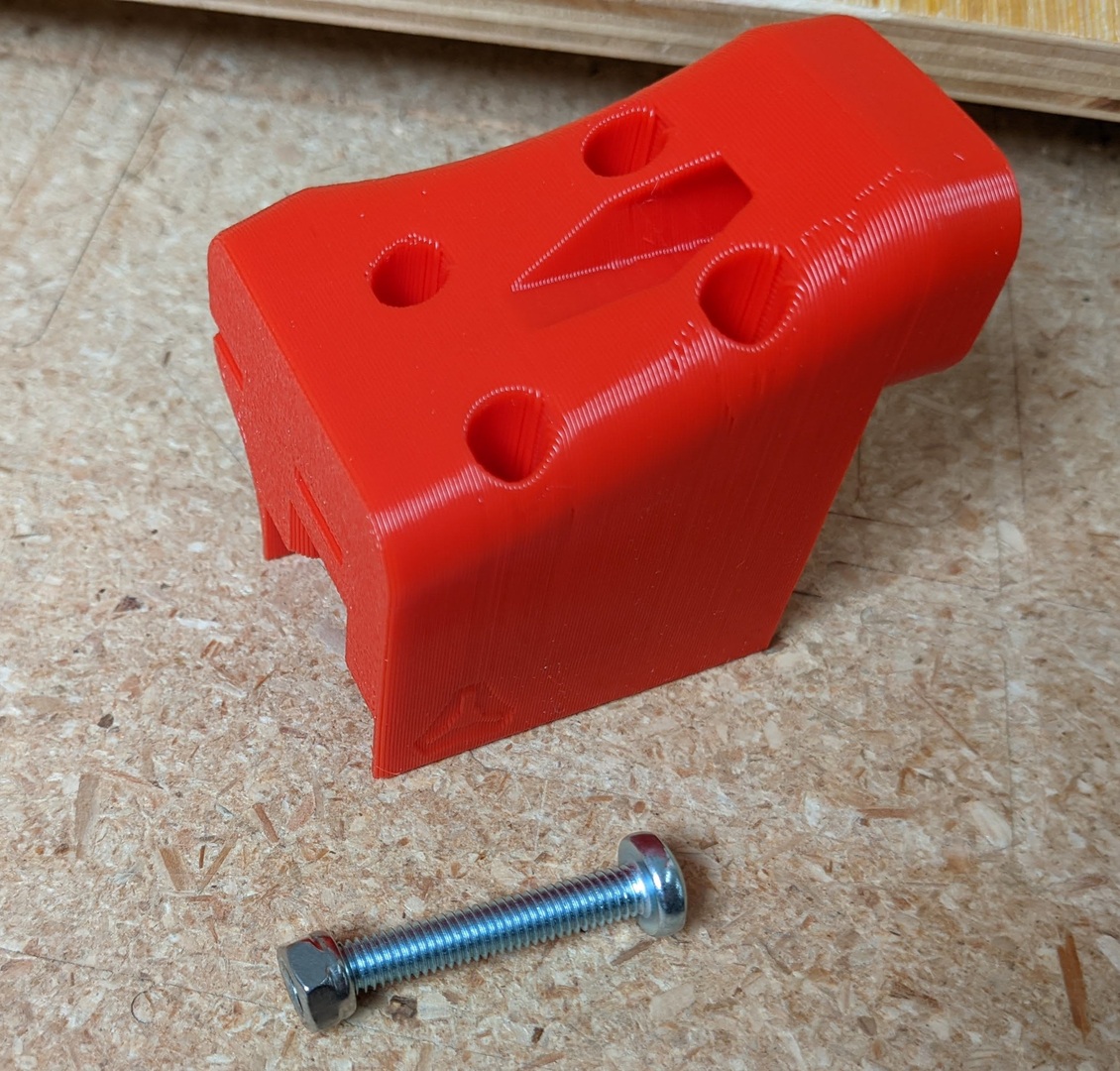
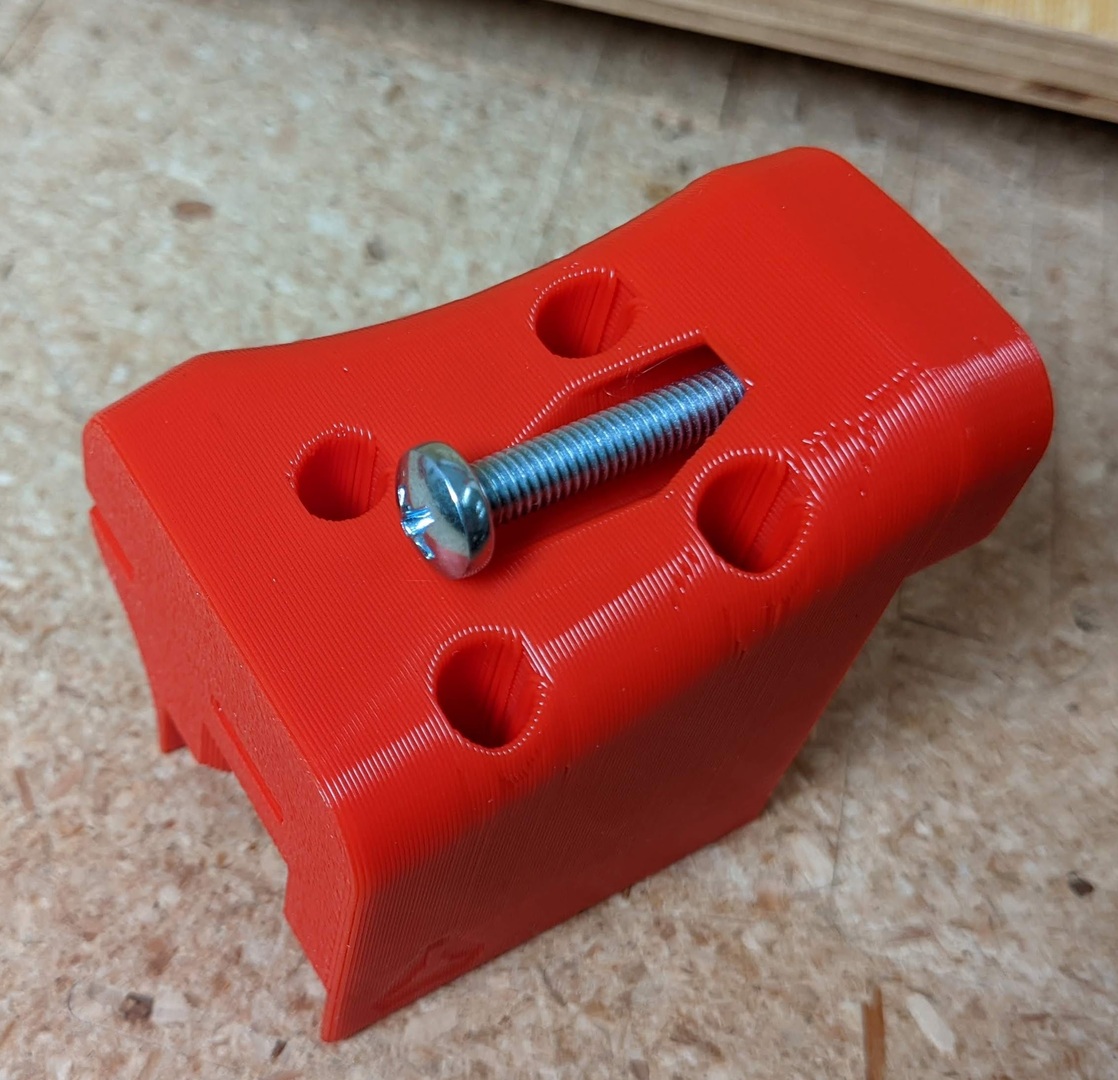
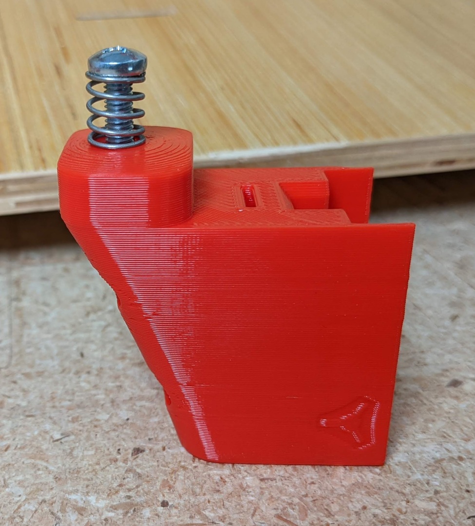
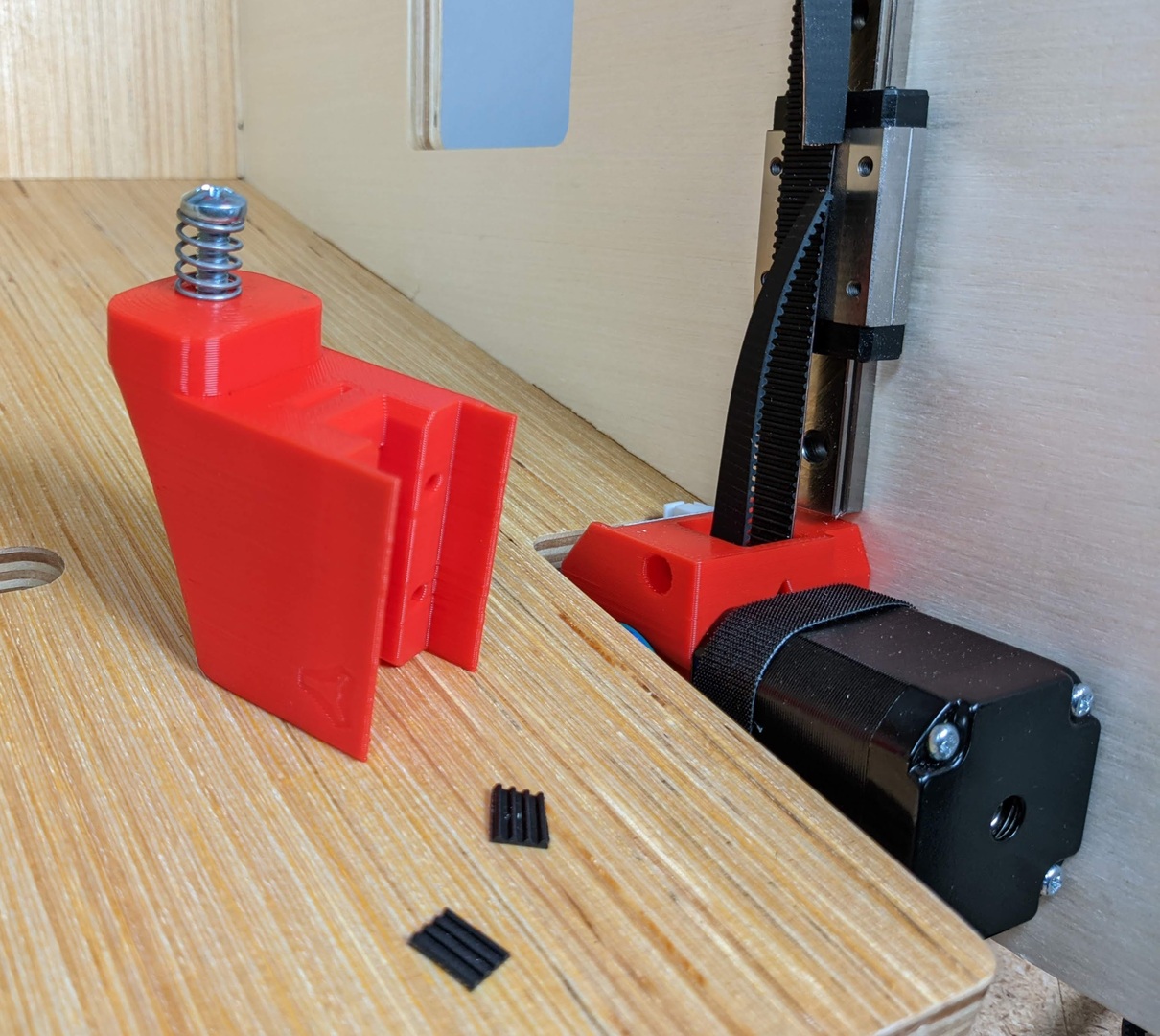
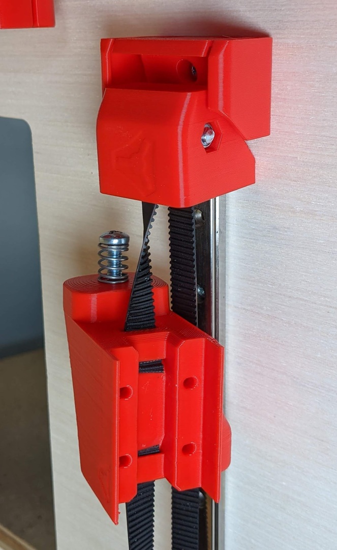
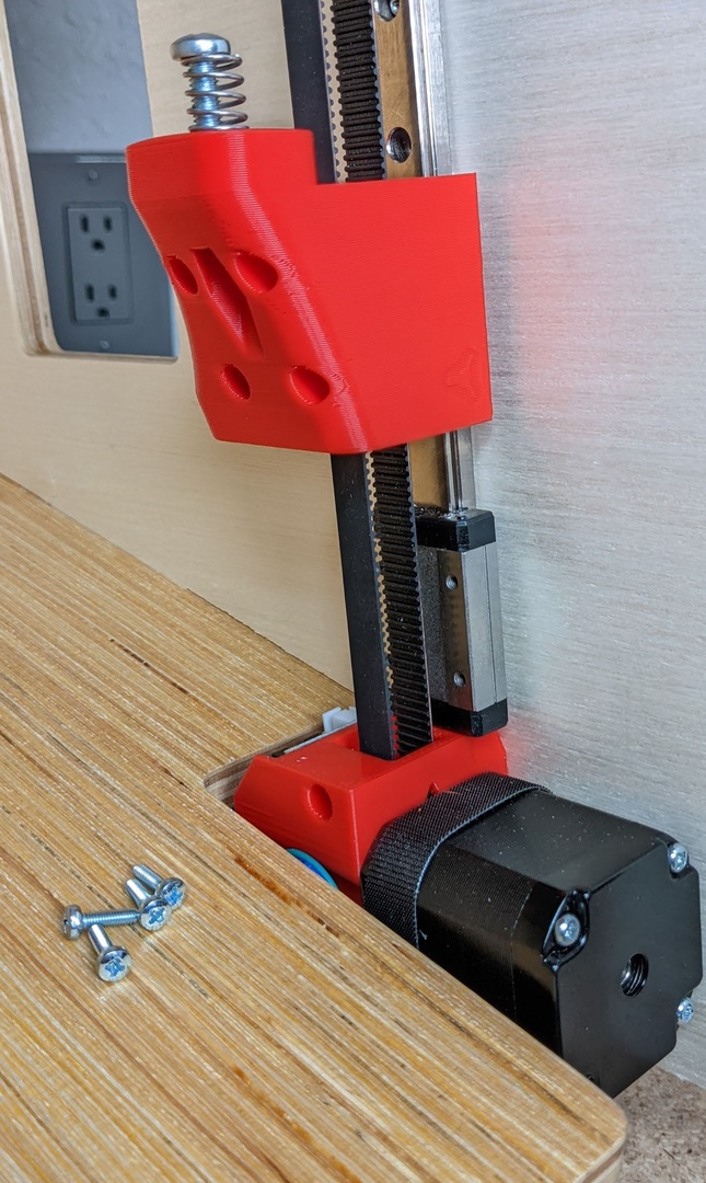
- Zbed Slider....my favorite part.
- Seat the nuts.
- For now add the spring and screw to hold the nut in place.
- Belt locks, 4 teeth long.
- Lock the bottom in place first.
- Now lock the top in place.
- You can remove the top idler braket to make this easier.
- A little trial and error is needed.
- The top idler can adjust up to 5mm of slack or more if you are not running wires on top.
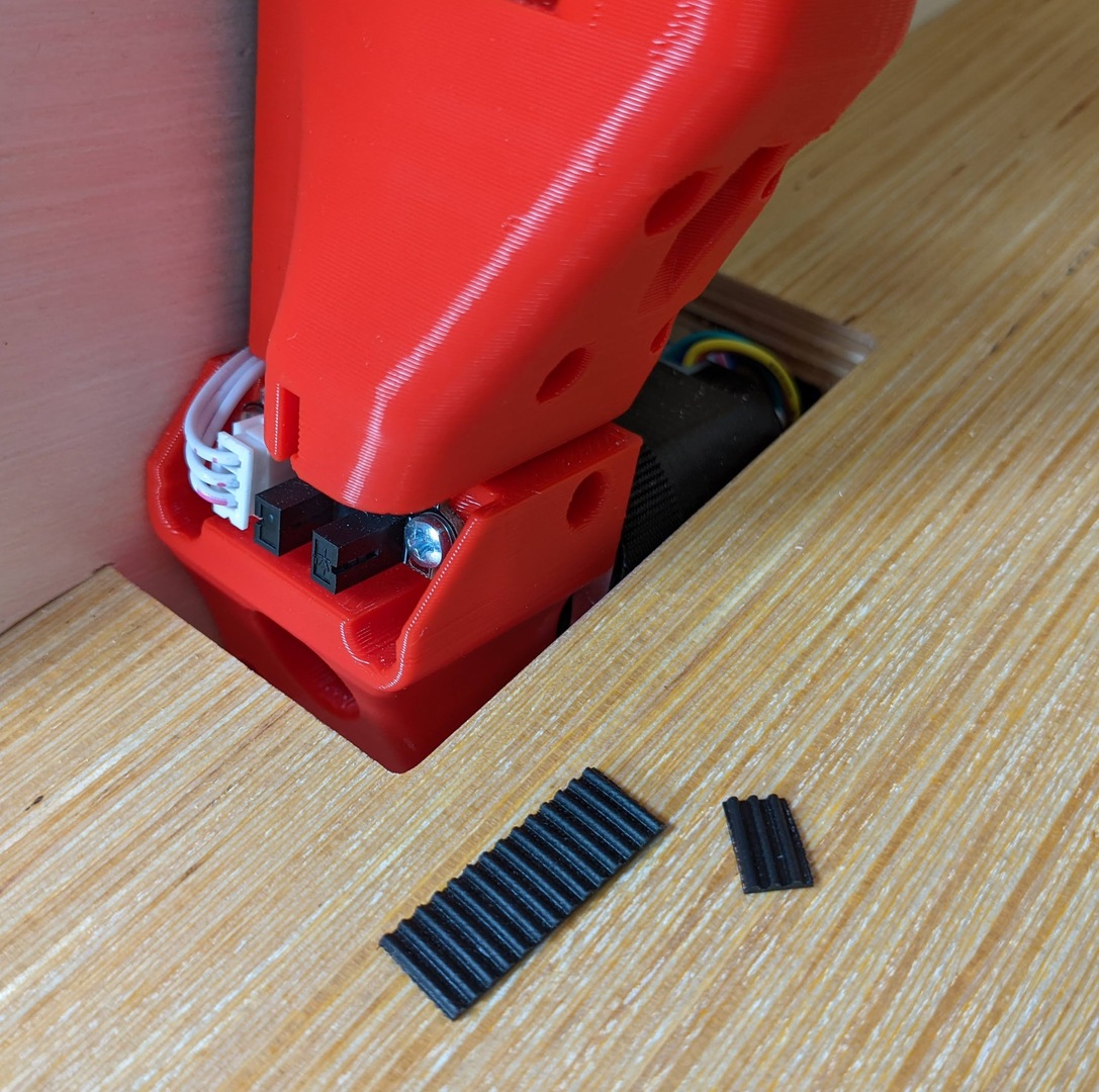
- Make sure to cut the belt flush.
- Mount using M3x10mm screws.
- Adjust the belt tension to be equal in all three and not too tight.
- 3-3.5 teeth for the trigger locks.
- Make the triggers just long enough to not hit the bottom when fully lowered or they can stay bent.
- Make sure they are centered.
- Looking good right?!?
